
Updated 2026-10-17
Issuing an incomplete horizontal flow wrapper Request for Quotation (RFQ) that states only nominal product dimensions and average line speed causes $18,000 to $65,000 in post-order forming-box rework, 2.5% to 6.0% registration and seal-crush film rejects, and 4 to 10 weeks of delayed Factory Acceptance Testing (FAT) and commissioning downtime. A complete flow wrapper requirements checklist—structured as an engineering User Requirements Specification (URS) traceable to PMMI OpX One Voice FAT protocols—must lock down four physical and operational envelopes before comparing vendor quotes: three-axis product dimensional extremes (L_prod x W_prod x H_prod min/nominal/max tolerances, tray/collation geometry, and surface tack/temperature), flat rollstock web width (W_film = 2(W_prod + H_prod) + 2W_fin + C_allowance) and ASTM D1894 coefficient of friction, required surge speed capacity (Q_design = (Q_upstream / OEE) * k_surge) and infeed phasing, and rotary versus box-motion cross-sealing jaw geometry verified against ASTM F88 / F1921 and EN 415-10 / ISO 12100 standards.
Engineering summary: Structure every horizontal Form-Fill-Seal (HFFS) RFQ around verifiable min/nominal/max dimensional tolerances (such as the Syntegon Pack 202 baseline envelope of L_prod = 40 to 565 mm, W_prod = 12 to 250 mm, H_prod = 6 to 110 mm, and W_film <= 450 to 650 mm), size your wrapper's design speed (Q_design) at 1.25x to 1.35x upstream continuous oven or cooling-tunnel discharge to recover from splice and minor-stop accumulation, specify ASTM D1894 outer film-to-metal kinetic COF mu_k <= 0.25 to 0.28 with a >= 35 °C seal initiation window, and mandate a 30 to 60 minute continuous PMMI OpX Factory Acceptance Test (FAT) running your actual production rollstock and worst-case product samples before shipment.
| URS / RFQ requirement domain | Standard engineering baseline or governing equation | Why it must be locked before comparing flow wrapper quotes |
|---|---|---|
| Three-axis product & pack envelope (L_prod x W_prod x H_prod) | Min / nominal / max in mm (Syntegon Pack 202 reference baseline: L = 40–565 mm, W = 12–250 mm, H = 6–110 mm) + tray/stack count & surface state | Fixes forming-box throat geometry, lug-chain pitch, and rotary jaw center distance; quoting on average size alone causes corner clipping on +3 sigma products |
| Flat film web width (W_film) & cut-off pitch (L_cut) | W_film = 2(W_prod + H_prod) + 2W_fin + C_allowance; L_cut = L_prod + k_H*H_prod + 2W_crimp + 2C_jaw; 76 mm (3 in) core, max OD 350–400 mm (≤35 kg) | Determines whether standard 450 mm or wide 650 mm backstand is required and verifies print eye-mark repeat length before ordering cylinders |
| Rollstock structure, SIT window, & ASTM D1894 COF | FDA 21 CFR 177.1520 / 175.105 compliance; outer film-to-metal kinetic COF μ_k = 0.18–0.28; sealant SIT 85–115 °C (or 20–24 °C cold seal at 1.5–3.5 MPa) | Prevents forming-shoulder web drag, fin-wheel tracking drift, and thermal seal burn-through during speed ramps |
| Required surge speed capacity (Q_design) & infeed phasing | Q_design = (Q_upstream / OEE) * k_surge (with OEE = 0.85–0.92 and k_surge = 1.15–1.25); manual lug chain vs servo smart-belt phase feeder + NPNB | Ensures the wrapper can clear accumulated upstream backlog after a film splice without dumping product to floor waste |
| Cross-sealing jaw kinematics (Rotary vs Box-Motion) | 1-up / 2-up / 3-up rotary crimper (35–90 ms dwell, up to 150–600+ ppm) vs box-motion long-dwell head (250–1,000 ms dwell, ULMA FM 300 / Pack 303 LD) | Matches jaw clearance and thermal dwell time to product height (H_prod > 45–55 mm) and high-barrier / MAP laminate gauge (65–120 μm) |
| Plant utilities, safety compliance, & PMMI OpX FAT protocol | 208–240 / 380–480 VAC 3-phase, 6 bar (80 psi) dry air; UL 508A, EN 415-10 / EN 415-3, ISO 12100; 30–60 min FAT run w/ ASTM F88 peel ≥ 3.5 N/15 mm | Aligns electrical/pneumatic drops, interlocked jaw guarding, and measurable good-pack yield (≥99.2%–99.5%) before machine release |
Why Do Incomplete Flow Wrapper RFQs Cause Forming-Box Rework and FAT Delays?
When a buyer sends three machinery suppliers a one-paragraph email stating "We need a flow wrapper for a 100 x 50 x 25 mm bar at 150 packs/min," each supplier quotes a fundamentally different machine class. Across industrial horizontal Form-Fill-Seal (HFFS) portfolios—documented in Syntegon's horizontal flow wrapper series (Pack 103, Pack 202, Pack 303 LD, and Pack 403) and ULMA Packaging's flow pack HFFS range (FR 100, FR 200, FR 305, and FM 300)—one vendor may quote an entry-level manual-infeed top-reel wrapper rated at 150 cuts/min mechanical peak speed on thin 25 um clear BOPP, while another engineers a servo-phased bottom-reel wrapper with a 200 packs/min surge buffer, chilled carry bedplate, and 2-up rotary jaws for metallized barrier film. Review our flow wrapper price guide, flow wrapper types comparison, and how flow wrapping works to see how each subsystem alters project scope.
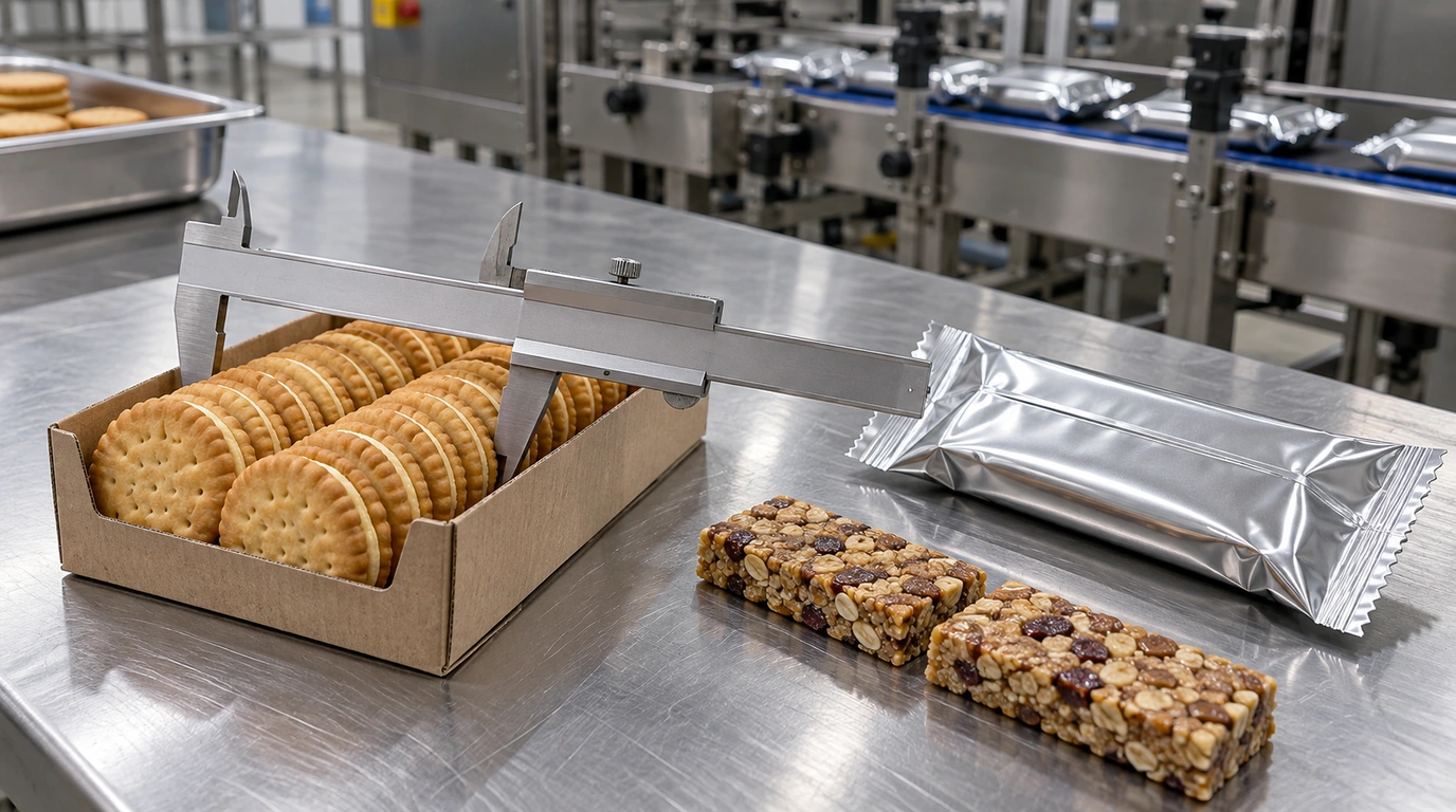
Under the PMMI OpX Leadership Network "One Voice Factory Acceptance Tests" framework, every engineering omission in the initial User Requirements Specification (URS) surfaces as an expensive mechanical failure during commissioning:
- Quoting Nominal Dimensions Instead of Three-Sigma Baked/Enrobed Extremes: Baked cookies, proofed buns, and chocolate-enrobed bars routinely vary by
±3 to ±6 mmin width and height due to oven spring, enrobing bottom "feet," or warped paperboard trays. A fixed forming box machined to nominal dimensions (e.g., 50.0 mm width) jams whenever a+4 mmoversized bar enters the throat, while a lug chain pitched for nominal length crushes trailing product tails into the rotary cross-sealing jaws. - Confusing Mechanical Nameplate Speed (
cuts/min) with Required Surge Capacity (Q_design): A wrapper's catalog max speed (e.g., 150 ppmon a1-upcrimper inSyntegon Pack 202reference literature) represents mechanical capability under ideal empty or free-flowing reference conditions. If an upstream oven or cooling tunnel discharges140 bars/mincontinuously, a150 ppmwrapper has only7%speed headroom—meaning every90-secondmanual film-reel splice forces operators to dump210 unwrapped barsinto floor scrap bins because the line lacks20% to 25%catch-up surge speed. - Omitting Film
ASTM D1894Friction, Caliper, and Cold-Seal vs Heat-Seal Structure: Specifying "standard flow-wrap film" hides whether the line will run25 umcoextruded BOPP (requiring 35 to 60 ms rotary jaw dwell at 125 °C),85 umlaminated PET/PE for Modified Atmosphere Packaging (requiring 300 to 600 ms box-motion dwell on an ULMA FM 300 or Syntegon Pack 303 LD), orFDA 21 CFR 175.105pattern-registered cold-seal film. Furthermore, unverified outer film-to-metal friction (ASTM D1894kinetic COFmu_k > 0.35) causes film drag over the forming collar, necking the web and throwing print registration off by±4 to 8 mm. - Unaligned Factory Acceptance Test (
FAT) Run Conditions: Without a written URS checklist specifying30 to 60 minutesof uninterrupted FAT production on the buyer's actual printed rollstock and worst-case product samples, a pre-shipment test often consists of a3-minuteburst using narrow clear test film and wooden dummy blocks—hiding seal-jaw heat soak, sticky residue accumulation, and eye-mark tracking drift until the machine arrives at your plant.
| URS subsystem & mandatory checklist inputs | Required engineering units & reference baseline | Subsystem sized by this input | Dominant Failure Mode & Mechanical Prevention |
|---|---|---|---|
| 1. Product Dimensional Envelope & Surface State (L_prod, W_prod, H_prod, mass, temperature, tack/fragility) | Min / nominal / max in mm (±3σ tolerances); mass (g); infeed core/surface temp (°C); water activity aw & bare-steel COF (ASTM D1894 μ_k) | Forming box throat (fixed vs adjustable), top-reel vs bottom-reel inverted path, chilled bedplate, and chain lug pitch | Failure mode: Oversized (+3σ) baked/coated products jamming forming throat or sticky bottoms buckling on top-reel deadplate -> Prevention: Size forming box to max tolerance + 4–6 mm clearance and specify bottom-reel inverted HFFS (ULMA FR 305) when μ_k ≥ 0.65 |
| 2. Rollstock Laminate, Core & Optical Registration Spec (W_film, L_cut, structure, caliper, SIT, COF, eye mark) | Flat width W_film (mm); repeat L_cut (mm); gauge (μm); sealant SIT (°C); ASTM D1894 outer COF μ_k ≤ 0.25–0.28; 76 mm core; 5×10 mm eye mark | Backstand width (450 vs 650 mm), dancer tension servo, fin-wheel profile, and two-way photoelectric eye-mark registration loop | Failure mode: High outer film COF (μ_k > 0.35) dragging on forming shoulder or low-contrast eye mark causing ±5 mm cut drift -> Prevention: Mandate ASTM D1894 outer μ_k = 0.18–0.28 and a solid 5×10 mm contrast eye mark in a clear 15 mm edge lane |
| 3. Upstream Infeed Pitch, Phasing & Surge Speed Capacity (Q_upstream, OEE, k_surge, arrival layout) | Continuous arrival rate Q_upstream (ppm); target OEE (0.85–0.92); surge factor k_surge (1.15–1.25); single-lane vs multi-row cooling tunnel | Wrapper design speed Q_design, manual lug chain vs multi-belt servo phase feeder (PF5 / smart belt), and automatic zero-speed splicer | Failure mode: Wrapper sized at 1.0× oven speed backing up cooling tunnel during 90 s manual film splices -> Prevention: Specify Q_design ≥ 1.25–1.35× Q_upstream with a 4-to-5 belt servo phase feeder and automatic reel splicer |
| 4. Sealing Jaw Kinematics, Utilities & FAT Protocol (Rotary vs Box-Motion, VAC/bar, EN 415-10, FAT duration) | Jaw dwell t_dwell (ms) & 1-up/2-up/3-up center distance; 208–480 VAC, 6 bar dry air; UL 508A / EN 415-10; 30–60 min FAT w/ ASTM F88 ≥ 3.5 N/15 mm | Rotary vs box-motion cross-seal head, MAP gas-flush lance, interlocked safety tunnel guarding, and FAT sign-off gate | Failure mode: Short-dwell rotary jaws clipping tall products (H_prod > 50 mm) or failing ASTM F88 peel on 80 μm barrier film -> Prevention: Specify box-motion long-dwell jaws (250–600 ms) or 2-up wide-center rotary jaws and verify via 60-min FAT + carbon impression |
How Do Your URS Inputs Govern Forming Boxes, Film Unwinds, and Sealing Jaws?
Every line item in your flow wrapper sizing, flow wrap film width and bag length, and manual vs automatic feeding calculation directly selects hardware subassemblies on the wrapper frame:
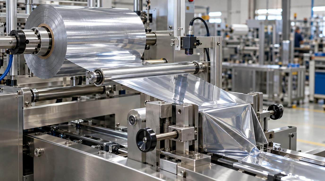
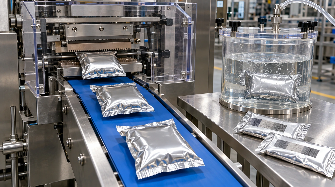
- Fixed Size-Specific Forming Box vs Universal Adjustable Forming Box (
Syntegon Pack 202 / ULMA Pack AdjusterBaselines): The forming box folds the flat film web (W_film) around the product cross-section (W_prod x H_prod). A fixed (dedicated) quick-change forming box is precision-bent for a single cross-section (tolerance ±3 mm), folding the web without wrinkles at150 to 600+ ppmand swapping out tool-lessly in2 to 4 minutes. An adjustable universal forming box uses handwheel leadscrews (with digital counters or motorized axes) to vary width and height across multiple SKUs (e.g., W_prod = 35 to 180 mm), but requires careful corner-tension tuning when switching between flat cookies and tall trays. - Top-Reel Lug-Chain vs Bottom-Reel (
Inverted) Belt-to-Film Architecture: Rigid, dry, uniform products (individually wrapped biscuits, trays, soap bars, hardware) run on a top-reel flighted lug-chain HFFS (ULMA FR 200 / Syntegon Pack 202), where polymer snap-on chain lugs push the product across a stainless deadplate into the film tube with a bottom fin seal. Soft, sticky, multipack-untrayed, or deformable products (cold-pressed fruit/protein bars, soft bakery dough, loose sliced groupings) require a bottom-reel (inverted) belt-to-film HFFS (ULMA FR 305baseline), where the product transfers across a3 to 6 mmknife-edge nosebar directly onto the moving bottom film web and seals the fin on top. Compare application details in our sticky bar flow wrapping guide, individual vs multipack cookie guide, and bread flow wrap vs bagging guide. - 1-Up / 2-Up / 3-Up Rotary Crimping Jaws vs Box-Motion Long-Dwell Jaws (
Syntegon Pack 202 vs Pack 303 LD / ULMA FM 300): On a rotary cross-sealing wrapper, heated serrated jaws rotate continuously on twin shafts. A1-upjaw (one knife pair per revolution) handles long or moderately tall packs up to~150 ppm;2-up(up to 250 ppm) and3-up(up to 350 to 600+ ppm) jaws multiply output at the same shaft RPM (up to 50 m/minfilm speed onPack 202), but reduce chord clearance for tall products and keep thermal dwell brief (35 to 90 ms). A box-motion (long-dwell) wrapper moves the upper and lower jaws horizontally alongside the moving film tube in a D-cam trajectory (maintaining 250 to 1,000 ms of flat parallel contact), which is mandatory for thick barrier laminates (65 to 120 um), tall loaves/trays (H_prod = 55 to 120 mm), and Modified Atmosphere Packaging (MAP). - Film Unwind Tension, Eye-Mark Registration, and No-Product-No-Bag (
NPNB) Interlocks: Entry-level wrappers use a single spindle with mechanical friction braking, whereas continuous industrial lines specify dual pneumatic self-centering76 mmspindles with servo-motorized dancer-arm tension control (holding web tension within ±1.5 N) and an automatic zero-speed splicer so reel changes at400 mmmax OD (35 kgreel weight) cause zero line stops. Two-way photoelectric registration sensors read a printed5 x 10 mmcontrast eye mark to phase the cutting head within±1.0 mm, while optical No-Product-No-Bag (NPNB) and misplaced-product jaw arrest sensors pause the film feed if an infeed lug arrives empty or out of pitch.
| Subsystem choice in URS / RFQ | Standard engineering baseline & operating window | Best-fit product & production scenario | Dominant Failure Mode & Mechanical Prevention |
|---|---|---|---|
| Dedicated Drop-In Quick-Change Forming Box vs Universal Adjustable Forming Box | Drop-in: fixed W_prod × H_prod (±3 mm), 2–4 min tool-less swap; Adjustable: handwheel/counter width & height range (15–25 min setup) | Drop-in: high-speed (150–600 ppm) repeatable SKUs; Adjustable: contract packers running low-volume variable dimensions (<120 ppm) | Failure mode: Diagonal film wrinkling and fin-seal edge drift after manual adjustable-former handwheel changes -> Prevention: Specify dedicated drop-in formers (or digital Siko counters + ULMA Pack Adjuster recipes) whenever width shifts >15–25 mm |
| 1-Up / 2-Up / 3-Up Rotary Crimping Head vs Box-Motion Long-Dwell Head | Rotary: 35–90 ms dwell, 150 ppm (1-up) / 250 ppm (2-up) / 350+ ppm (3-up); Box-motion: 250–1,000 ms dwell, 50–150 ppm, H_prod up to 110–130 mm | Rotary: high-speed bars, biscuits, candies in 20–45 μm BOPP; Box-motion: MAP bakery/trays, tall products (H > 50 mm), 65–120 μm barrier laminates | Failure mode: 2-up/3-up rotary jaws clipping tall product ends or producing weak (<2.0 N/15 mm) seals on thick PET/PE laminates -> Prevention: Specify box-motion long-dwell jaws when H_prod > 45–55 mm or film gauge ≥ 65 μm requires t_dwell ≥ 250 ms |
| Single Friction-Brake Unwind vs Dual-Spindle Servo Tension + Auto-Splicer | Single: manual 90–180 s reel change every 45–75 min; Dual + Auto-Splicer: zero-speed splice in <1.5 s at up to 50 m/min web speed | Single: batch manual lines (<80 ppm); Dual + Auto-Splicer: continuous oven/enrober lines (≥120 ppm) where stops cause upstream scrap | Failure mode: Web snap or ±6 mm eye-mark registration jump as reel diameter drops from 400 mm to 90 mm core -> Prevention: Specify closed-loop servo dancer tension control and automatic splicing for continuous upstream lines |
| Manual Lug-Chain Infeed vs Multi-Belt Servo Phase Feeder (Smart Belt) | Manual lug chain: 50–80 ppm per operator; 3-to-5 stage servo smart belt (Syntegon PF5 baseline): 100–500+ ppm contactless electronic phasing | Manual: short batch runs or hand-collated trays; Servo smart belt: continuous oven/cooling-tunnel discharge, fragile biscuits, or sticky bars | Failure mode: Operators missing chain lugs above 75 ppm (wasting film) or backpressure crushing fragile/sticky products -> Prevention: Enable optical No-Product-No-Bag (NPNB) + misplaced-product jaw arrest and specify servo belt phasing above 80–100 ppm |
Physical-Threshold Engineering Rules for Your Flow Wrapper URS
Apply these four quantitative rules-of-thumb when filling out your flow wrapper requirements checklist to eliminate mis-sized proposals before issuing Purchase Orders:
- Product-Height-to-Jaw-Radius & Laminate Dwell Rule (
H_prod&t_dwell->Rotary vs Box-Motion Crimpers): If maximum product or tray height exceedsH_prod > 45 to 55 mm(or the ratio of product height to rotary cutting-circle radius exceeds H_prod / R_jaw > 0.55) OR your barrier laminate thickness exceeds65 to 120 um(such as PET/PE, PA/PE, or paper/poly requiring t_dwell >= 250 to 600 ms for hermetic ASTM F88 peel strength >= 4.0 N/15 mm and MAP residual oxygen < 0.5% to 1.0%) -> specify a box-motion (long-dwell) cross-sealing head (ULMA FM 300orSyntegon Pack 303 LDbaseline) or a wide-center1-uprotary head rather than a standard2-up / 3-uprotary crimper. Multi-up rotary jaws enter the film tube at a steep chord angle that clips tall product shoulders and provides only35 to 90 msof nip contact, causing channel leaks at the longitudinal fin-seal crossover (T-junction). - Upstream Surge-Speed Buffer & OEE Catch-Up Rule (
Q_designvsQ_upstream->Servo Phase Feeder + Auto-Splicer): If the flow wrapper receives product directly from a continuous thermal process (bakery tunnel oven, chocolate enrobing cooling tunnel, or continuous bar slitter) discharging atQ_upstream >= 80 to 150 packs/min-> specify rated continuous wrapper and servo phase-feeder capacity in your URS atQ_design >= 1.25 to 1.35 * Q_upstream(accounting for OEE <= 0.88 to 0.92 and an upstream buffer recovery multiplier of k_surge = 1.15 to 1.25) together with a dual-spindle automatic reel splicer. Sizing a wrapper at1.0xnominal upstream output leaves zero catch-up speed to drain accumulation buffers after a minor stop or film splice, forcing operators to divert good product to floor waste. - Rollstock
ASTM D1894Coefficient of Friction (COF), Seal Window & Eye-Mark Contrast Rule: If specifying rollstock film to run at linear web speedsv_film >= 25 to 50 m/min(>= 120 to 300 packs/min) across a stainless-steel forming shoulder -> require in your film URS an outer film-to-metal kinetic COF (ASTM D1894) ofmu_k = 0.18 to 0.28(strictly < 0.30), a minimum35 to 55 °Cdifferential between the inner copolymer Seal Initiation Temperature (SIT = 85 to 115 °C) and the outer print layer's heat distortion temperature, and a solid monochromatic registration eye mark (>= 5 mm feed-direction height x 10 mm width) inside a15 mmgraphic-free edge track. Outer COF above0.35induces stick-slip web tension oscillation over the forming collar, causing fin-seal edge wander (> ±2.5 mm) and erratic cross-jaw cuts. - Multi-SKU Dimensional Spread & Changeover Tooling Rule (
Delta_W_prod->Drop-In Formers vs Adjustable Box): If your checklist includes>= 3 to 5 SKUsper shift whose product widths differ byDelta_W_prod > 15 to 25 mm(or whose flat web width W_film changes by > 30 mm) -> specify one dedicated pre-set drop-in quick-change forming box per width family (2 to 4 minutetool-less swap with repeatable dowel pins) plus HMI recipe storage (100+ recipes) and digital position indicators (or servo auto-positioning axes) rather than relying on a single handwheel-adjusted universal forming box. Re-adjusting a universal former across wide width steps consumes25 to 45 minutesand150 to 400trial packs per changeover.
Quantitative Sizing Equations and Worked Arithmetic Examples for URS Preparation
Before sending your checklist to suppliers, run these three explicit engineering calculations to verify that your requested product envelope, rollstock width, surge speed, and FAT acceptance counts are mathematically consistent. Compare detailed film math in our flow wrap film guide and HFFS machines overview.
1. Flat Film Web Width (W_film) and Cut-to-Cut Bag Repeat Pitch (L_cut)
W_film (mm) = 2 * (W_prod + H_prod) + 2 * W_fin + C_allowance
L_cut (mm) = L_prod + k_H * H_prod + 2 * W_crimp + 2 * C_jaw
- Variables:
W_prod,H_prod,L_prod= maximum (+3 sigma tolerance) product or loaded tray width, height, and length (mm);W_fin= single folded longitudinal fin-seal height (typically 12 to 15 mm, matching theSyntegon Pack 2026 to 15 mmfin-seal spec);C_allowance= forming-box drape and tracking clearance (10 to 20 mm; add2 * G_gussetif side gussets are tucked);k_H= end-film slope factor (0.85 to 1.0for standard pillow packs;1.15for tall vertical-wall trays);W_crimp= single transverse end-seal jaw width (12 to 20 mm;20 to 25 mmcombined twin-crimp head);C_jaw= single-side product-to-jaw safety clearance (10 to 18 mmper end to prevent product crush or radiant heat melt). - Worked example: Suppose your URS specifies a baked biscuit U-board tray whose nominal size is
135 x 62 x 25 mm, but whose maximum+3 sigmabaked/warped envelope isL_prod = 140 mm,W_prod = 65 mm, andH_prod = 28 mm, wrapped withW_fin = 15 mm,C_allowance = 14 mm,k_H = 0.90,W_crimp = 15 mm, andC_jaw = 12 mm:- Required flat rollstock web width:
W_film = 2 * (65 + 28) + 2 * (15) + 14 = 186 + 30 + 14 =230 mmflat film width (confirming that a standard 450 mm backstand covers the SKU with 220 mm of spare width capacity). - Required cut-to-cut bag pitch (eye-mark repeat):
L_cut = 140 + (0.90 * 28) + 2 * (15) + 2 * (12) = 140 + 25.2 + 30 + 24 =219.2 mm(specified as 220 mmprinted eye-mark repeat pitch).
- Required flat rollstock web width:
2. Required Surge Speed Capacity (Q_design), Linear Film Velocity (v_film), & Crimper Multi-Up Check
Q_design (packs/min) = (Q_upstream / OEE) * k_surge
v_film (m/min) = (Q_design * L_cut) / 1,000
- Variables:
Q_upstream= continuous upstream discharge rate from oven, cooling tunnel, or depositor (packs/min);OEE= target operational availability factor accounting for date-coder ribbon swaps, minor sensor stops, and quality checks (0.85 to 0.92);k_surge= surge recovery multiplier (1.15 to 1.25) required so the smart-belt phase feeder can drain accumulated upstream backlog without overfilling buffers;v_film= linear film web velocity (m/min) at surge speed. - Worked example: Your upstream bakery cooling conveyor discharges
Q_upstream = 160 trays/mincontinuously into a flow wrapper operating atOEE = 0.88with a requiredk_surge = 1.20(20%surge catch-up buffer) on theL_cut = 220 mmbag pitch calculated above:- Required wrapper and phase-feeder surge design speed:
Q_design = (160 / 0.88) * 1.20 = 181.82 * 1.20 =218.2 -> 220 packs/minrequired continuous surge rating (37.5%above the160 ppmaverage discharge rate). - Required linear film velocity at surge speed:
v_film = (220 packs/min * 220 mm) / 1,000 =48.4 m/min. Comparing against theSyntegon Pack 202reference specification (max 50 m/min film speed; 150 ppm on 1-up crimper vs 250 ppm on 2-up crimper) proves that a1-upcrimper (150 ppm max) will bottleneck the line by70 ppm, so your URS must explicitly specify a2-uprotary crimper head (rated to 250 ppm).
- Required wrapper and phase-feeder surge design speed:
3. PMMI OpX FAT Continuous Run Pack Count (N_FAT_packs), Rollstock Footage (L_FAT_film), & Max Reject Limit (N_reject_max)
N_FAT_packs = Q_target * t_FAT_min
L_FAT_film (m) = (N_FAT_packs * L_cut) / 1,000
N_reject_max = N_FAT_packs * (1 - eta_yield_min)
- Variables:
Q_target= sustained FAT test speed (packs/min);t_FAT_min= uninterrupted FAT test duration per SKU (30 to 60 minutesunderPMMI OpX One Voice FATprotocols);eta_yield_min= minimum acceptable net good-pack yield (typically 0.995 = 99.5%pass rate acrossASTM F88seal integrity,±1.5 mmprint registration, and zero product crush). - Worked example: For a
t_FAT_min = 60 minuteuninterrupted FAT validation run atQ_target = 180 packs/min(L_cut = 220 mm,eta_yield_min = 99.5%):- The FAT run must produce
N_FAT_packs = 180 * 60 =10,800 consecutive packs, requiring at leastL_FAT_film = (10,800 * 220) / 1,000 =2,376 linear meters(plus 300 m setup allowance = 2,676 m) of actual printed production rollstock shipped to the OEM factory, with no more thanN_reject_max = 10,800 * (1 - 0.995) =54 rejected packsacross the entire60-minutetest.
- The FAT run must produce
5-Year Total Cost of Ownership (TCO) Ledger: Incomplete RFQ vs Engineering URS & FAT Protocol
Cutting corners on your pre-purchase requirements checklist shifts massive hidden costs into post-delivery re-tooling, changeover scrap, and unscheduled line downtime over a 5-year equipment lifecycle. Compare how a complete URS and FAT protocol protects your capital budget across our flow wrap packaging pillar, bakery packaging machine hub, cookie packaging machines, bread packaging machines, cereal bar packaging machines, candy packaging machines, chocolate bar packaging machines, and non-food flow wrapping, as well as process comparisons in flow wrap vs shrink wrap and HFFS vs VFFS.
| 5-Year TCO cost & risk category | Scenario A: Ad-Hoc Email RFQ (Nominal Size & Average Speed Only; 3-Min Dummy FAT) | Scenario B: Structured Engineering URS (±3σ Tolerances + Film Spec; 15-Min Sample FAT) | Scenario C: Full PMMI OpX Traceable URS + Drop-In Formers + 60-Min Production-Film FAT |
|---|---|---|---|
| Post-delivery forming-box, lug-pitch & crimper re-tooling cost | $28,000–$62,000 in Year 1 (emergency field replacement of undersized forming box, lug chain pitch, and 1-up to 2-up crimper shaft) | $4,500–$9,000 over 5 yrs (minor guide-rail and nosebar shimming during SAT commissioning) | $0 unplanned rework (forming shoulders, 2-up/box-motion jaws, and phase-feeder surge speed verified against ±3σ extremes at FAT) |
| 5-year upstream surge overflow & manual-splice product scrap ($0.22/unit) | $211,200 over 5 yrs (1.0× speed wrapper lacks surge catch-up; 0.5% upstream product dumped during manual reel splices & micro-stops) | $59,136 over 5 yrs (1.20× surge capacity specified, but manual reel changes still pause wrapper for 90 s every hour) | $16,896 over 5 yrs (1.30× Q_design surge buffer + automatic zero-speed splicer + optical NPNB keeps splice waste <0.04%) |
| 5-year film registration, COF drag & T-junction seal leak scrap | $168,000 over 5 yrs (3.5% rollstock + product rework from unverified outer COF >0.35 and insufficient rotary jaw dwell on barrier film) | $48,000 over 5 yrs (1.0% scrap; ASTM D1894 COF and SIT window locked in URS) | $24,000 over 5 yrs (0.5% scrap; box-motion / Flex Set jaw pressure and two-way eye-mark loop validated over 10,800-pack FAT) |
| 5-year multi-SKU changeover downtime (3 changeovers/day × 250 days/yr) | 2,187 hrs lost over 5 yrs (35 min/changeover tweaking universal handwheel former without recipes = 437 hrs/yr lost) | 937 hrs lost over 5 yrs (15 min/changeover using Siko digital counters and written setup sheets = 187 hrs/yr lost) | 312 hrs lost over 5 yrs (5 min/changeover using tool-less drop-in formers, self-centering chucks, and HMI recipe recall = 62 hrs/yr lost) |
| Commissioning & Site Acceptance Test (SAT) ramp-up delay | 6–10 weeks delayed full production (waiting on replacement forming collars, UL 508A / EN 415-10 guard retrofits, and film re-slitting) | 1–2 weeks SAT ramp-up (minor fine-tuning ofupstream conveyor handoff and encoder scaling) | 2–4 days turnkey SAT sign-off (machine ships pre-validated on buyer production film, recipes, and utility drops) |
Interactive Copyable & Downloadable Flow Wrapper Requirements Checklist (URS / RFQ)
Use the interactive checklist below to assemble your complete engineering brief. Click Copy checklist, Download .txt, or Download .csv to export all 18 specification fields for your internal project team and machinery suppliers:
1. Product dimensional envelope & physical state
- Product name, SKU list, and clear photos/video of unpacked product, bottom surface, and target finished pack Required
- Three-axis dimensional extremes (Min / Nominal / Max Length × Width × Height in mm, ±3σ baked/coated tolerances) and unit mass (g) Required
- Pack collation format: single piece, flat pile stack, on-edge slug, or paperboard/plastic tray (include tray flange & draft dimensions) Required
- Surface & thermal behavior at infeed: core/surface temperature (°C), chocolate softening point (27–32 °C), water activity (aw), bare-steel friction (ASTM D1894 μ_k), or crumb shedding Required
2. Rollstock film, web geometry & registration
- Film laminate structure & gauge (e.g., 30 μm BOPP/CPP heat-seal, 40 μm met-BOPP pattern cold-seal, or 80 μm PET/PE MAP barrier film) Required
- Calculated flat film web width (W_film in mm), cut-to-cut bag repeat pitch (L_cut in mm), and fin-seal vs lap-seal width (12–15 mm) To confirm
- Seal Initiation Temperature (SIT in °C) or cold-seal nip pressure (MPa), plus ASTM D1894 outer film-to-metal kinetic COF (μ_k ≤ 0.25–0.28) To confirm
- Reel core ID (76 mm / 3 in standard), max outer diameter (OD ≤ 350–400 mm), max reel weight (≤ 35 kg), winding direction (wind chart #), and 5×10 mm eye-mark artwork drawing To confirm
3. Upstream output, surge speed & feeding interface
- Continuous upstream arrival rate Q_upstream (packs/min), target OEE (85%–92%), and required surge design speed Q_design (1.25–1.35× Q_upstream) Required
- Infeed loading architecture: manual lug-chain loading (50–80 ppm/operator), magazine feeder, multi-belt servo phase feeder (smart belt), or bottom-reel inverted nosebar transfer Required
- Upstream & downstream equipment handoff: conveyor bed height (e.g., 850 ±50 mm), upstream cooling tunnel/oven interface, and downstream checkweigher/metal detector/cartoner signals Optional
- Number of daily SKU changeovers and required changeover time (<5–10 min via drop-in quick-change forming boxes vs adjustable universal former) Required
4. Sealing head, options, utilities & safety compliance
- Transverse sealing head type: 1-up / 2-up / 3-up continuous rotary crimper vs box-motion long-dwell head (250–600+ ms dwell for tall products or MAP) To confirm
- Auxiliary process options: automatic zero-speed reel splicer, No-Product-No-Bag (NPNB), misplaced-product jaw arrest, 10–15 °C chilled bedplate, MAP gas flush, date coder, or euro-slot/gusset Optional
- Destination country/city, plant electrical supply (e.g., 208–240 V or 380–480 V 3-phase 50/60 Hz), compressed air (6 bar / 80 psi dry air), and footprint/ceiling limits Required
- Machine safety, sanitation & control standards: EN 415-10 / EN 415-3, ISO 12100, OSHA 29 CFR 1910.212 interlocked guarding, UL 508A / CE panel, IP65 washdown, and PLC platform preference To confirm
5. Factory Acceptance Test (FAT) & sample trial protocol
- FAT continuous run duration per SKU (e.g., 30–60 min uninterrupted at Q_target) using buyer-supplied production rollstock and actual product extremes To confirm
- Quantifiable FAT pass/fail criteria: net good-pack yield (≥99.2%–99.5%), ASTM F88 seal peel strength (N/15 mm), vacuum leak test (ASTM D3078 / F2095), and timed changeover demo To confirm
What to Send Us to Start Your Flow Wrapper Engineering Review
| Engineering item to send us | How our application engineers use it | Preferred format or measurement detail |
|---|---|---|
| 1. Product photos, weight & 3-axis dimensional extremes (L × W × H) | Calculates flat web width (W_film), cut pitch (L_cut), forming-box throat clearance, and rotary vs box-motion jaw center distance | Min / nominal / max Length × Width × Height in mm (across ≥20 production pieces or trays) + unit weight in grams + smartphone video of product handling |
| 2. Product surface condition, temperature & pack arrangement | Selects between top-reel lug-chain HFFS, bottom-reel inverted belt-to-film HFFS, and 10–15 °C chilled carry bedplates | Packing-point core/surface temperature (°C), coating/stickiness notes (chocolate, caramel, fragile wafer, warm bread), and pieces per pack / tray drawing |
| 3. Rollstock film datasheet & eye-mark artwork (or shelf-life target) | Verifies ASTM D1894 COF, seal initiation temperature (SIT), cold-seal vs heat-seal crimper profile, and reel backstand width (450 vs 650 mm) | Converter PDF datasheet (film structure, μm gauge, SIT °C, COF) and dieline PDF showing eye-mark size/position—or mark as "recommend film structure" |
| 4. Upstream discharge speed (Q_upstream) & line layout sketch | Sizes wrapper surge speed capacity (Q_design = 1.25–1.35× Q_upstream), servo smart-belt phase feeder, and automatic reel splicer | Continuous upstream output (units/min), arrival pattern (hand-fed, single conveyor, or multi-row cooling tunnel), and available floor L × W × H (m) |
| 5. Plant utilities, destination & FAT acceptance expectations | Configures transformer/voltage tap, UL 508A / CE / EN 415-10 compliance, spare-parts kit, and pre-shipment FAT validation schedule | Destination port/city, voltage/Hz (e.g., 230V/480V 60Hz), compressed air bar/psi, and target FAT run duration / seal test method |
Reference Factory Acceptance Test (FAT) & sample trial record template (PMMI OpX traceable)
- Product
- Baked sandwich biscuit multipack in fluted paperboard U-board tray (185 g net mass)
- Dimensions
- Nominal 135 × 62 × 25 mm; verified ±3σ production envelope L = 132–140 mm, W = 60–65 mm, H = 23–28 mm
- Pack format
- Single U-board tray pillow pack with 15 mm bottom longitudinal fin seal and 15 mm serrated transverse end crimps
- Film
- 35 μm coextruded metallized BOPP/CPP heat-seal laminate (FDA 21 CFR 177.1520; ASTM D1894 outer kinetic COF μ_k = 0.22; SIT = 98 °C); W_film = 230 mm, L_cut = 220 mm eye-mark repeat on 76 mm core
- Machine configuration
- Cantilevered 4-axis servo top-reel HFFS flow wrapper (Syntegon Pack 202 / ULMA FR 200 class) with 4-belt servo phase feeder, dedicated drop-in forming box, 2-up rotary crimper, and dual-spindle auto-splicer
- Running conditions
- 60-minute uninterrupted PMMI OpX FAT run at Q_target = 180 packs/min (Q_design surge tested to 220 packs/min = 48.4 m/min film speed); fin heaters 145 °C, rotary jaws 155 °C, ambient 21 °C / 48% RH
- Inspection method
- 100% optical registration & NPNB monitoring across 10,800 packs; carbon-impression jaw nip uniformity check; destructive ASTM F88 seal peel and ASTM D3078 vacuum chamber leak sampling every 15 minutes (n = 40 packs)
- Result
- 10,774 accepted packs / 26 rejected packs (99.76% net good-pack yield vs ≥99.50% URS threshold); ASTM F88 cooled peel strength 4.6–5.2 N/15 mm; zero T-junction micro-leaks at -50 kPa vacuum; zero splice stops across 2 automatic reel transfers
- Limits
- Validated strictly for the tested 60–65 mm tray width and 35 μm met-BOPP/CPP structure; switching to >65 μm barrier laminate or tray height >48 mm requires re-verifying jaw dwell time and a dedicated forming box.
Send Your Completed Checklist, Product Photos & Dimensions on WhatsApp for an HFFS Engineering Review
Common Questions on Preparing a Flow Wrapper Requirements Checklist (URS / RFQ)
Why must a flow wrapper RFQ checklist include minimum and maximum product dimensions instead of only nominal size?
A horizontal flow wrapper folds a flat film web through a rigid stainless-steel forming box throat and indexes products between fixed-pitch chain lugs or phased belts. If you state only nominal dimensions (such as 100 x 50 x 25 mm) and your oven, enrober, or tray supplier produces +4 mm oversized pieces (104 x 54 x 29 mm), those pieces jam inside the forming collar, tear the film web, or get crushed by the rotary cross-sealing jaws. Specifying your ±3 sigma minimum, nominal, and maximum Length x Width x Height allows the OEM to size flat web width (W_film), jaw clearance, and dedicated vs adjustable forming boxes accurately.
How much surge speed capacity above my average line output should I specify in a flow wrapper URS?
You should specify a design surge capacity of Q_design = (Q_upstream / OEE) * k_surge, which typically equals 1.25x to 1.35x your continuous upstream discharge rate. For example, if an upstream oven or cooling tunnel discharges 160 bars/min continuously and the wrapper runs at 88% OEE with a 1.20x surge recovery factor, the wrapper and its servo phase feeder must be rated for 220 packs/min continuous operation. That 25% to 35% speed reserve allows the phase feeder to drain accumulated buffer queues after a film splice or minor stop without dumping product to floor scrap.
What film parameters are mandatory in a flow wrapper requirements checklist before a Factory Acceptance Test (FAT)?
Provide the complete converter datasheet specifying: (1) laminate material structure and total caliper in microns (e.g., 30 um BOPP/CPP or 40 um metallized BOPP with pattern cold seal); (2) Seal Initiation Temperature (SIT in °C) and sealing window, or cold-seal nip pressure (MPa); (3) ASTM D1894 outer film-to-metal kinetic coefficient of friction (mu_k = 0.18 to 0.28, strictly below 0.30 to prevent forming-box drag); (4) calculated flat web width (W_film), cut repeat pitch (L_cut), and 5 x 10 mm eye-mark registration dieline; and (5) reel core ID (76 mm / 3 in), maximum outer diameter (350–400 mm), and winding direction.
What constitutes a valid Factory Acceptance Test (FAT) protocol in a horizontal flow wrapper purchase contract?
Under PMMI OpX One Voice FAT guidelines, a valid HFFS Factory Acceptance Test requires running each contracted SKU continuously for 30 to 60 minutes at full target production speed using buyer-supplied production rollstock and actual product samples (including dimensional extremes). To pass FAT prior to crating and shipment, the machine must demonstrate >= 99.2% to 99.5% net accepted pack yield, verified ASTM F88 seal peel strength (>= 2.5–4.5 N/15 mm for cold seal or >= 3.5–6.0 N/15 mm for heat seal), zero vacuum leak failures, verified EN 415-10 / OSHA 29 CFR 1910.212 safety interlocks, and a timed format changeover within the URS limit.