
Updated 2026-10-17
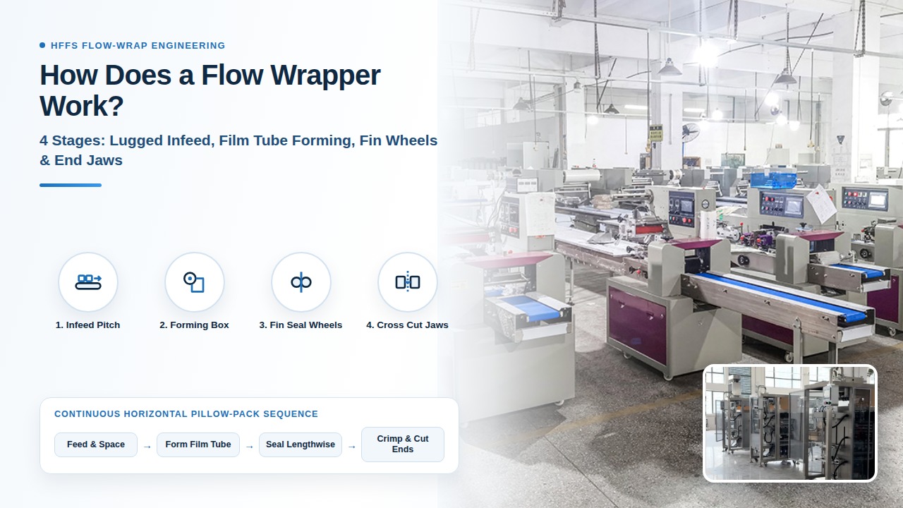
Mismatched pitch timing, forming-shoulder drag, or insufficient cross-jaw dwell time on a horizontal flow wrapper turns directly into crushed product tails in the end jaws, open longitudinal fin seams, and 40 to 90 meters of wasted film per reel splice. Understanding how does a flow wrapper work requires analyzing a Horizontal Form-Fill-Seal (HFFS) machine as five synchronized mechanical and thermal zones: infeed pitch metering, forming-box tube folding, longitudinal fin-wheel pull and sealing, transverse cross-sealing and cutting, and discharge inspection. Unlike vertical baggers that drop loose fill through a vertical tube, a horizontal flow wrapper transports discrete solid products—or trayed groups—along a horizontal plane while wrapping a single flat film reel around the product and sealing three sides into a pillow pack.
Engineering summary: A flow wrapper synchronizes product arrival pitch with flat web velocity so the film forms a continuous horizontal tube, seals the longitudinal seam via rotary fin wheels, and crimps and cuts the leading and trailing transverse end seals in a single jaw cycle between adjacent products.
| Input or subsystem | Standard baseline or source | Why it governs line setup |
|---|---|---|
| HFFS 5-stage process architecture | ULMA Flow Pack (HFFS) & Syntegon Pack series horizontal flow wrapper architecture | Establishes continuous horizontal web transport from flat reel unwind through forming box, fin wheels, and cross jaws |
| Entry-to-mid speed envelope (rotary) | ULMA FR 100 (entry-level servo) & Syntegon Pack 202 (up to 150–170 packs/min; film width up to 420–650 mm) | Sets baseline mechanical pitch, web speed, and 3-phase power (5 kVA at 230/400 V) for manual or semi-auto lines |
| High-dwell / MAP cross-sealing | ULMA FM 300 Box Motion (long-dwell head; up to 150 packs/min or 30 m/min web speed; 6 bar, 50 L/min air) | Replaces radial rotary pinch with a parallel orbital jaw path to extend hermetic seal dwell time on barrier films |
| Hot-tack vs cooled seal strength | ASTM F1921 (hot-tack strength immediately after sealing) & ASTM F88 (cooled fin/end seal peel strength) | Prevents longitudinal fin seams and end seals from splitting under product weight and internal gas pressure before cooling |
| Food-contact film & guarding compliance | FDA 21 CFR 177.1520 (olefin polymers) & OSHA 29 CFR 1910.212 / ISO 12100 point-of-operation guarding | Mandates compliant sealing layers and hard-wired safety interlocks over rotary knives and heated crimp jaws |
How the 5-Stage Horizontal Flow Wrapping Cycle Works as One Synchronized System
A horizontal flow wrapper operates by locking product spacing (infeed pitch) to film web advance (bag cut length) through either a common mechanical line shaft or multi-axis electronic camming. In continuous-motion operation, neither the product nor the film stops during sealing: the longitudinal fin wheels pull the folded film tube forward at constant linear velocity while the transverse sealing jaws accelerate to match film speed at the exact moment of cross-sealing and cutting.
Reference documentation from ULMA Packaging's Flow Pack HFFS guide and Syntegon's horizontal flow wrapper overview confirms that every industrial pillow pack depends on maintaining zero relative slip between the product, the forming tube, and the sealing interfaces. Compare the broader package format boundaries in our flow wrap packaging overview and HFFS machines guide.
| Process stage | Primary mechanical assembly | Controlled process variables | Dominant Failure Mode & Mechanical Prevention |
|---|---|---|---|
| Stage 1: Product infeed & pitch metering | Lugged chain conveyor with polymer pusher fingers, or dual-belt hugger/smart-belt phasing feeder | Chain pitch (mm), product arrival phase angle (deg), deadplate transfer gap (mm) | Product tail lags or bounces forward into the jaw cut zone -> Enable optical Misplaced Product Detection (MPD) and No-Product-No-Bag (NPNB) servo phase inhibit |
| Stage 2: Film unwind, registration & tube forming | Cantilevered film mandrel, dancer tension roller, photo-eye mark sensor, and fixed or adjustable forming box | Unwind brake tension (N), eye-mark offset (mm), forming collar entry angle and width clearance (mm) | Film web telescopes, wrinkles, or tears at forming shoulder corners -> Match forming-box throat width within +4 to +8 mm of product width and center the unwind mandrel |
| Stage 3: Longitudinal fin-wheel pull & sealing | 2 to 4 pairs of knurled rotary pull, heat-seal, and cold-fold wheels beneath (or above) the film tube | Wheel nip pressure (bar/N), heater PID temperature (°C), linear pull speed ratio (+0.5% to +1.5% lead) | Channel leaks or longitudinal seam splitting before cooling -> Balance ASTM F1921 hot-tack window with pre-heat wheel pair and dedicated unheated fold-over wheel |
| Stage 4: Transverse cross-sealing & cut-off | Rotary 1/2/3/4-jaw shafts or box-motion long-dwell head with internal flying anvil and serrated guillotine knife | Jaw temperature (°C), spring/pneumatic crimp force (N), dwell time (ms), cyclic velocity profile | End-seal blowouts at the center fin step or melted film on jaws -> Machine relief step in jaw serrations for the 4-layer fin fold and match jaw touch velocity to web speed |
| Stage 5: Discharge, inspection & handoff | Independent polyurethane outfeed belt, air-jet or pusher reject gate, checkweigher, and metal detector | Discharge belt overdrive (+5% to +12% over web speed), jaw-to-belt drop height (mm), reject timing (ms) | Finished pack stalls on exit and backs into the rotating lower jaw -> Run discharge belt 8–10% faster than film speed to pull cut packs clear of the jaw sweep radius |
Stage 1 — Product Infeed and Pitch Metering
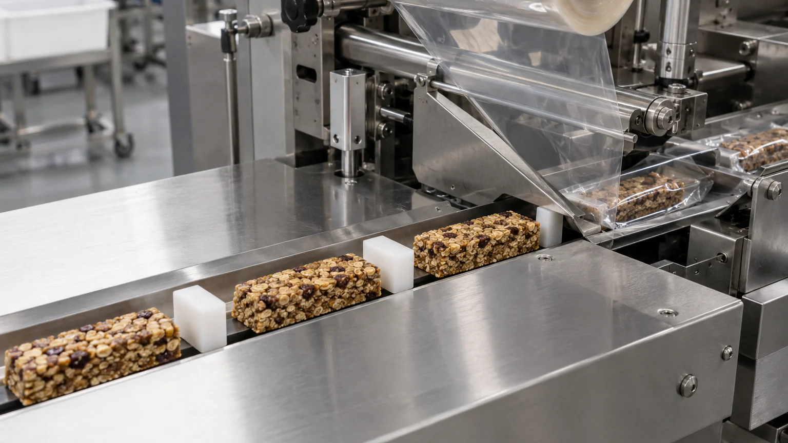
The infeed conveyor establishes the physical distance between consecutive products so each item enters the film tube inside its designated bag window. On standard top-reel machines, a stainless-steel bed plate carries a slotted chain fitted with replaceable polymer flight lugs (pusher fingers) spaced at a fixed mechanical pitch. Each lug pushes the trailing edge of one product toward the forming box while side guides keep the item aligned with the machine centerline.
When products are soft, sticky, fragile, or lack a rigid trailing edge—such as sticky protein bars, loose bakery stacks without trays, or flexible medical drapes—a rigid pusher lug will gouge or buckle the product. In those lines, engineers specify a bottom-reel (inverted) belt infeed where the unwinding film itself carries the product into the forming zone, or a multi-belt phasing feeder that meters gaps via servo speed matching. See manual feeding vs automatic feeding and sticky bar flow wrapping for upstream infeed selection rules.
Stage 2 — Film Unwind, Registration, and Tube Forming
The film unwind and forming station converts a flat roll of flexible packaging material into a continuous tube wrapped loosely around the moving product stream. A cantilevered reel holder supports the film roll (typically up to 420 mm wide on compact frames like the Syntegon Pack 202 or 600–650 mm on mid-frame machines like the ULMA FR 100 and FM 300), feeding the web through dancer rollers that damp tension spikes during acceleration and deceleration.
For printed film, an optical contrast sensor reads the printed registration eye-mark on every repeat and trims the servo differential between the fin wheels and the infeed chain so graphics stay centered on the pack face. The flat web then passes over the forming shoulder (forming box), which turns the outer edges of the film downward (on a top-reel wrapper) or upward (on a bottom-reel wrapper) until the two inner sealant layers meet in a vertical fin. Fixed-size forming boxes provide the highest geometric stability for dedicated single-SKU runs, whereas crank-adjustable forming boxes trade a slightly wider film allowance for rapid multi-width changeovers. Review flow wrap film structures for how film stiffness and coefficient of friction (COF) affect forming-box drag.
Stage 3 — Longitudinal Fin-Wheel Transport and Sealing
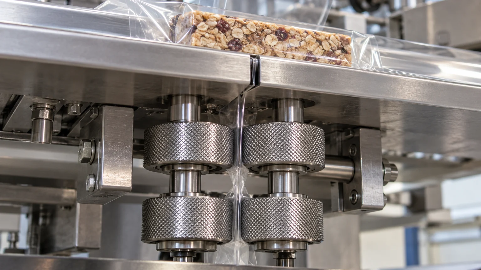
Longitudinal fin wheels perform two mechanical jobs simultaneously: they pull the film web off the reel through the forming box, and they weld the two overlapping edges of the film tube into a continuous lengthwise seam. As detailed in Syntegon's engineering breakdown of horizontal flow wrapper sealing and cutting, most industrial flow wrappers arrange two to four pairs of counter-rotating rollers along the longitudinal seam:
- First roller pair (cold pull / tension nip): Knurled or rubber-coated wheels grip the unsealed fin edges immediately after the forming box to maintain positive web tracking without thermal distortion.
- Second roller pair (heated fin-seal wheels): Electrically heated steel wheels with precision knurling apply controlled temperature (
typically 115–165 °C for BOPP/CPP laminates) and nip pressure to fuse the inner sealant layers (regulated under FDA 21 CFR 177.1520 for food-contact polyolefins). - Third roller pair (unheated fold-over or chill wheels): Tilts the hot vertical fin flat against the bottom (or top) of the pack and stabilizes the seal while it is still in its
ASTM F1921hot-tack state to prevent longitudinal seam leakage.
Two longitudinal seam geometries dominate production lines: a fin seal folds the two inner surfaces together (inner-to-inner), requiring only the inside layer of the film to be heat-sealable, whereas a lap seal overlaps the inner surface onto the outer surface (inner-to-outer), saving 15 to 25 mm of flat web width per roll but requiring compatible heat-seal coatings on both sides of the film. The dominant failure mode in Stage 3 is web misalignment or cold-tack channeling caused by uneven roller nip pressure; engineers prevent this root cause by pairing a cold pull wheel with an independently spring-loaded heated sealing pair.
Stage 4 — Transverse Cross-Sealing and Cut-Off Kinematics
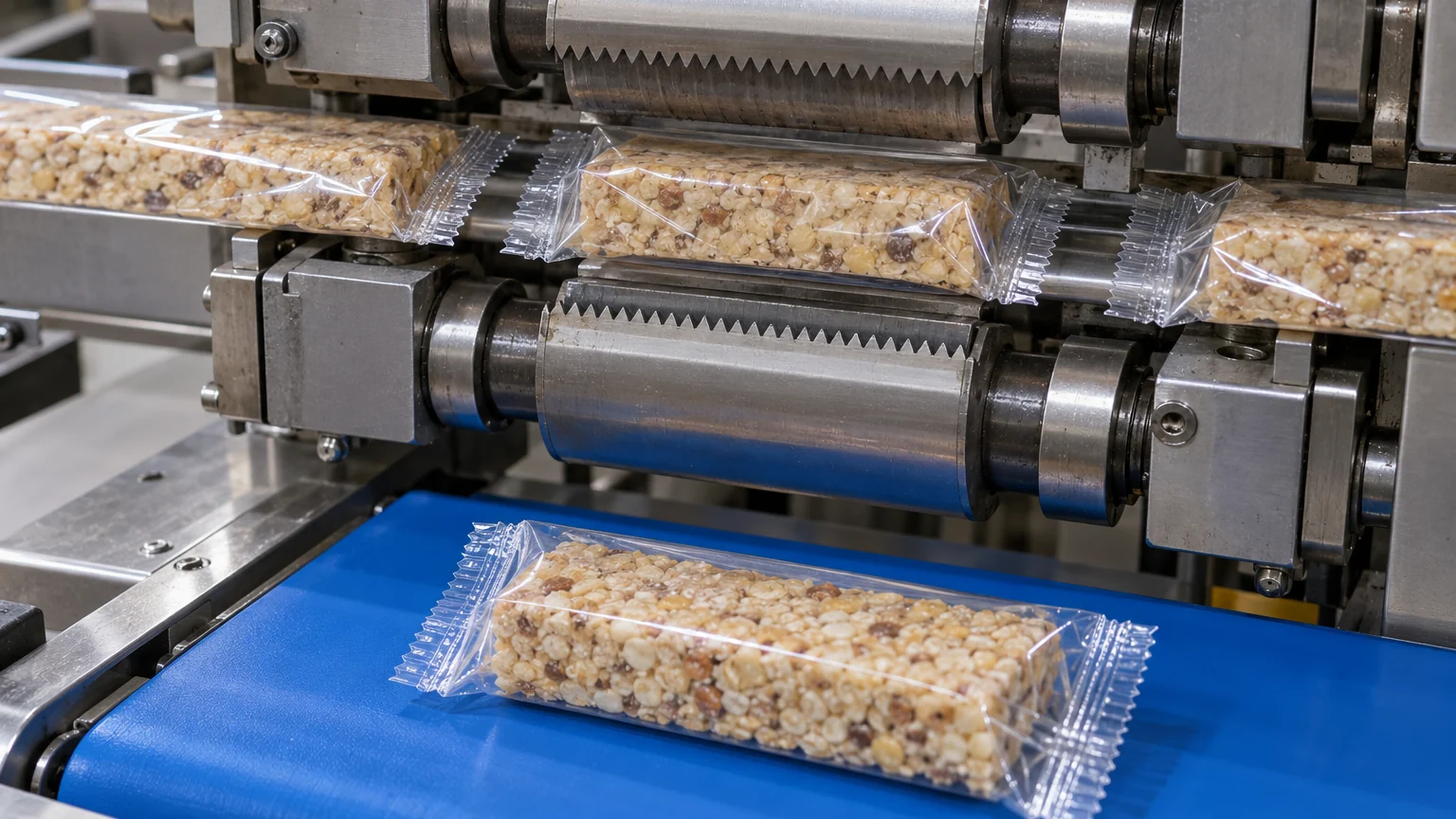
The transverse cross-sealing station creates the trailing end seal of the outgoing pack, the leading end seal of the next pack, and the knife cut that separates them in a single synchronized pass. Upper and lower cross-sealing shafts carry heated serrated jaws (1, 2, 3, or 4 jaws per shaft depending on bag length and target speed). Inside the upper jaw sits a hardened cutting knife; inside the lower jaw sits a spring-loaded or flying anvil.
As the jaws close between two consecutive products, the serrated crimpers compress and heat-seal the film tube (including the 4-layer center step where the folded longitudinal fin crosses the end seal) while the internal knife fires across the center of the crimp to sever the individual pillow pack. The primary failure mode at Stage 4 is end-seal contamination or center-step leakage when product crumbs enter the crimp zone or when radial jaw dwell is too short; optical Misplaced Product Detection (MPD) and relieved jaw serrations prevent both defects. Mechanical guarding and safety interlocks around the cross-jaw housing must satisfy OSHA 29 CFR 1910.212 and ISO 12100 point-of-operation standards so the drive stops immediately if an access cover is opened.
| Subsystem choice | Kinematic & thermal mechanism | Primary application envelope | Dominant Failure Mode & Mechanical Prevention |
|---|---|---|---|
| Rotary cross-sealing jaws (1–4 jaw heads) | Jaws rotate on fixed circular centers; electronic cam adjusts angular speed so jaw tangent velocity matches web velocity at contact | Standard pillow packs in BOPP, cold seal, or light laminates at 40–600+ packs/min where 25–60 ms seal dwell is sufficient | Product end clipping on tall items (>65–80 mm) due to radial sweep arc -> Increase jaw center distance, widen bag pitch allowance, or switch to box-motion kinematics |
| Box-motion (long-dwell D-cam) jaws | Jaw carriage travels horizontally with the film tube along a flat orbital D-path before opening and returning (e.g., ULMA FM 300) | Modified Atmosphere Packaging (MAP), thick barrier laminates (>50 um), and tall bakery/meat packs up to 150 packs/min (30 m/min) | Leaking corner gussets or incomplete gas flush at high speed -> Extend horizontal carriage dwell to 150–350 ms and pair with a stainless gas-flushing lance inside the forming tube |
| Top-reel lug-chain infeed | Film unwinds from above; longitudinal fin seal forms underneath the product; chain lugs push products over a slotted stainless bed | Rigid, uniform single pieces or trayed multipacks (biscuits, chocolate bars, boxed hardware, soap bars) | Soft or sticky product smears across the bed plate and jams at the deadplate gap -> Switch to bottom-reel belt feed or PTFE-coated low-friction transfer plates |
| Bottom-reel (inverted) belt infeed | Film unwinds from below the infeed plane; product rides directly on the moving web; fin seal forms on top of the pack | Fragile, limp, sticky, or multi-piece trayless products (soft dough, sticky cereal bars, leafy produce, medical kits) | Top fin seal obscures primary front-of-pack branding -> Offset the longitudinal fin toward the pack edge or orient the product upside-down before infeed |
Stage 5 — Discharge, Quality Inspection, and Downstream Handoff
Once the cross-jaw knife severs the film web, the finished pillow pack must clear the lower jaw sweep radius immediately before the next jaw lobe rotates upward. To guarantee positive separation, the discharge belt runs at a 5% to 12% linear speed overdrive relative to the film web velocity.
On automated packaging lines, the discharge conveyor transfers packs across a deadplate onto an inline checkweigher, X-ray or metal detector, and high-speed air-blast or pusher reject gate. For hermetic or MAP lines, quality control protocols pair inline vision inspection of the crimp zone with off-line destructive peel testing under ASTM F88 (cooled seal strength) and ASTM F1921 (hot-tack strength) to verify that the four-layer center fin intersection holds without micro-channels.
Physical-Threshold Engineering Rules for Configuring a Flow Wrapper
Use these four physical-threshold rules to select the right mechanical architecture before issuing an RFQ or booking a factory trial. For a full comparison of machine families, see flow wrapper types, flow wrap vs shrink wrap, and HFFS vs VFFS.
- Cross-Sealing Kinematics (Rotary vs Box-Motion Long-Dwell): If required hermetic seal dwell time exceeds
120 to 150 mson barrier laminates thicker than50 to 60 umor on gas-flushed MAP packs at web speeds above18 to 25 m/min, or if product height exceeds75 to 90 mm-> prioritize a box-motion (long-dwell) cross-sealing head over a rotary jaw head because the flat orbital carriage maintains parallel pressure for150 to 400 msand eliminates the wide radial entry/exit sweep that clips tall product shoulders. - Film Unwind Orientation (Top-Reel Lug vs Bottom-Reel Inverted): If product flexural stiffness cannot bridge a
10 to 15 mmdeadplate transfer gap without sagging, or if surface tackiness causes drag against stainless-steel bed plates -> prioritize a bottom-reel (inverted) flow wrapper over a top-reel lug-chain wrapper because the unwinding film web carries the product continuously into the forming tube with zero sliding friction against fixed metal guides. - Thermal Sensitivity (Heat-Seal vs Cold-Seal Jaw Setup): If product surface melting temperature is below
32 to 35 °C(enrobed chocolate, probiotic coatings, low-melt wax or confection) and target line throughput exceeds250 to 300 packs/min-> prioritize pattern-applied cold-seal film with unheated serrated pressure jaws over thermal heat-seal jaws because elastomeric cold-seal adhesive bonds via contact pressure alone, eliminating radiant heat soak during short machine stops. - Drive Architecture (Single-Motor Mechanical vs Multi-Axis Servo): If a line runs more than
2 to 3 SKU changeovers per 8-hour shiftacross bag lengths varying by more than20%, or if upstream product arrival is irregular -> prioritize a 3-to-5-axis servo-driven HFFS with electronic camming (NPNBandMPD) over a mechanically linked chain-and-gearbox machine because independent servo axes adjust pitch, eye-mark offset, and jaw dwell velocity from HMI recipes in under5 minuteswithout mechanical change gears.
Sizing Equations and Worked Arithmetic Examples
Accurate flow wrapper setup relies on four deterministic equations linking product dimensions (L_prod, W_prod, H_prod) to flat film width, cut pitch, jaw shaft RPM, and net shift output. Detailed dimensional worksheets are available in flow wrapper sizing and flow wrap film width and bag length calculations.
1. Flat Film Web Width (W_web)
W_web = 2 * (W_prod + H_prod) + 2 * W_fin + C_forming
- Variables:
W_prod= product width (mm);H_prod= product height (mm);W_fin= single fin-seal flange width (typically12 to 15 mm);C_forming= forming-tube folding and tracking clearance (10 to 16 mm). - Worked example: Wrapping a rectangular bar of width
W_prod = 40 mmand heightH_prod = 22 mmwith aW_fin = 15 mmfin fold andC_forming = 12 mmtube allowance requiresW_web = 2 * (40 + 22) + 2 * (15) + 12 = 124 + 30 + 12 = 166 mm(specify a standard165 mmor170 mmslitted reel).
2. Cut-Off Bag Pitch (L_cut) and Linear Web Speed (V_film)
L_cut = L_prod + H_prod + 2 * W_crimp + C_jaw
V_film (m/min) = (N_ppm * L_cut) / 1000
- Variables:
L_prod= product length (mm);H_prod= product height allowance for film drape at both ends (mm);W_crimp= width of one serrated end seal (12 to 18 mm);C_jaw= total clearance between product ends and jaw crimp (16 to 24 mm);N_ppm= target speed (packs/min). - Worked example: For a
L_prod = 110 mmbar (H_prod = 22 mm),W_crimp = 14 mmper end, andC_jaw = 18 mmtotal clearance,L_cut = 110 + 22 + 28 + 18 = 178 mm. AtN_ppm = 150 packs/min, linear web velocity isV_film = (150 * 178) / 1000 = 26.70 m/min(0.445 m/s).
3. Rotary Jaw Shaft Speed (RPM_jaw) and Seal Dwell Time (t_dwell)
RPM_jaw = N_ppm / Z_jaws
t_dwell (ms) = (L_arc / (V_film / 60))
- Variables:
Z_jaws= number of sealing jaws per rotating shaft (1, 2, 3, or 4);L_arc= effective radial or flat sealing contact path length (m). - Worked example: Running
N_ppm = 150 packs/minon a twin-jaw head (Z_jaws = 2) drives the jaw shaft atRPM_jaw = 150 / 2 = 75.0 RPM. With a16 mm(0.016 m) radial nip arc at0.445 m/sweb speed, rotary dwell time ist_dwell = 0.016 / 0.445 = 0.036 s = 36 ms(whereas a box-motion head with an80 mmflat carriage stroke at the same web speed delivers0.080 / 0.445 = 180 msof seal dwell).
4. Net Shift Good-Pack Output (Q_net)
Q_net = N_ppm * 60 * T_shift * OEE_avail * (1 - R_scrap)
- Variables:
T_shift= shift duration (hours);OEE_avail= net machine running availability after reel changes, cleaning, and upstream stops;R_scrap= film and startup reject ratio. - Worked example: Running
N_ppm = 150 packs/minover an8-hourshift with84%availability (OEE_avail = 0.84) and1.5%startup/registration scrap (R_scrap = 0.015) yieldsQ_net = 150 * 60 * 8 * 0.84 * 0.985 = 59,572 good packs/shift.
Total Cost of Ownership (TCO) Hidden-Cost Ledger and Factory Trial Setup
Evaluating a flow wrapper solely on base purchase price overlooks the operational losses that accumulate across a three-year production horizon. Compare machine budget tiers in flow wrapper price, non-food industrial setups in non-food flow wrapping, and our downloadable flow wrapper requirements checklist.
| Cost driver | Mechanical / basic line impact | Multi-axis servo / engineered line impact | Engineering mitigation to specify in RFQ |
|---|---|---|---|
| Film registration & reel-splice scrap | 40–90 m of printed film wasted per splice or restart while manually re-phasing eye-mark offset (2.5–4.0% annual film waste) | 6–15 m wasted per splice; servo eye-mark registration locks within 3–5 bag repeats (<0.8% annual film waste) | Specify dual-reel unwind with automatic splicer or servo self-centering eye-mark phase recovery |
| SKU changeover downtime | 25–45 min per changeover to swap chain lug pitch, adjust forming box, and re-time jaw eccentricity | 3–8 min per recipe recall on HMI with motorized jaw center height and adjustable forming box | Order dedicated drop-in forming boxes for top-volume SKUs and recipes tied to servo axis positions |
| Product-in-jaw crush & knife damage | Unmetered product tails get crushed in heated jaws, requiring 15–30 min solvent scrape-down and premature knife replacement | Optical MPD sensor inhibits jaw closure when a product crosses the cut zone out of phase, ejecting a double-length uncut bag | Mandate optical Misplaced Product Detection (MPD) and quick-change cartridge heaters/knives |
| Utilities & pneumatic consumption | 3–5 kVA electrical draw on rotary servo frames; up to 50 L/min at 6 bar dry air on pneumatic/box-motion assemblies | Regenerative common DC bus servos lower peak kVA; all-electric jaw actuation eliminates compressed-air moisture drift | Verify plant 3-phase voltage stability and specify ISO 8573-1 Class 1.4.1 air filtration if pneumatic gusseters/jaws are used |
What to Send Us for a Process and Sizing Evaluation
| Item | Why we need it | Example format |
|---|---|---|
| Product dimensions (L x W x H) & weight range | Determines flat film width (W_web), cut pitch (L_cut), forming-box throat geometry, and jaw center distance | 110 x 40 x 22 mm (±2 mm tolerance), 48 g granola bar; 20 sample pieces shipped for trial |
| Surface condition & thermal sensitivity | Dictates top-reel lug chain vs bottom-reel belt feed and heat-seal vs cold-seal jaw tooling | Chocolate-coated bottom (melts above 32 °C), slightly tacky oat top surface, no tray |
| Film structure & barrier target | Sets fin-wheel temperature window, jaw serration pitch, and rotary vs box-motion dwell time | 25 um metalized BOPP / 20 um CPP laminate, 15 mm fin seal, nitrogen flush to <1.5% residual O2 |
| Target speed (packs/min) & shift schedule | Calculates linear web velocity (V_film), jaw RPM, and whether manual or automatic feeding is required | 150 packs/min nominal, 180 packs/min peak, two 8-hour shifts/day, 4 SKU changeovers/shift |
| Upstream arrival & downstream handoff | Aligns infeed conveyor height, phasing belt interface, and discharge overdrive for checkweigher/cartoner | Arrives single-file on 850 mm high cooling tunnel belt; discharges to inline checkweigher + metal detector |
Send Product Dimensions & Photos on WhatsApp for a 5-Stage Line Review
How does a flow wrapper seal packages continuously without stopping the film web?
Longitudinal fin wheels rotate at constant surface velocity to pull and weld the lengthwise seam while the film moves forward. At the transverse cross-sealing station, the rotating or orbital jaws accelerate via electronic camming so their horizontal tangent velocity matches the linear film velocity (V_film) during the brief crimp and cut window, then adjust speed between cuts to match the target bag length.
When should a line use a bottom-reel (inverted) flow wrapper instead of a top-reel lug-chain machine?
Specify a bottom-reel (inverted) flow wrapper when the product is too soft, limp, sticky, or multi-piece to be pushed across a slotted stainless-steel bed by a chain lug without deforming or jamming at the transfer gap. On an inverted wrapper, the film unwinds beneath the product stream and acts as a continuous carrier conveyor right into the forming box, sealing the longitudinal fin on top of the pack.
Why do pillow packs leak at the center of the end seal even when jaw temperature is increased?
The center of the transverse end seal crosses the folded longitudinal fin seam, creating a transition from two layers of film to four layers. If the jaw serration profile lacks a machined relief step for that four-layer thickness, or if rotary dwell time (typically 25–60 ms) is too short for heat to penetrate all four layers without burning the two-layer wings, micro-channels form at the fin step. Profiling the jaw serrations or switching to a box-motion long-dwell head resolves the leak.
How does No-Product-No-Bag (NPNB) prevent film waste when upstream supply has gaps?
An optical sensor at the infeed detects whether a product is present in each lug pocket. When a pocket is empty, the multi-axis servo controller halts the film unwind, fin wheels, and cross-sealing jaws in open-park position while the infeed conveyor continues indexing until the next product arrives, eliminating empty sealed bags.
Related guides
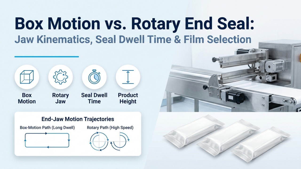
Compare Flow Wrapper Types and Configurations
Rotary or box motion? Top film or bottom film? Compare the feeding, film path and end-seal choices in a flow wrapper proposal.
Read more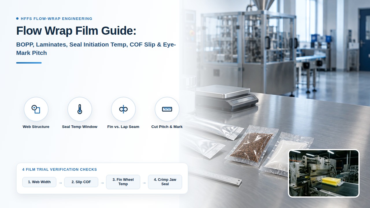
Choosing Flow Wrap Film for Your Product and Machine
Choosing flow wrap film starts with the product and required seal. Gather the film specification, reel dimensions and samples for compatibility testing.
Read more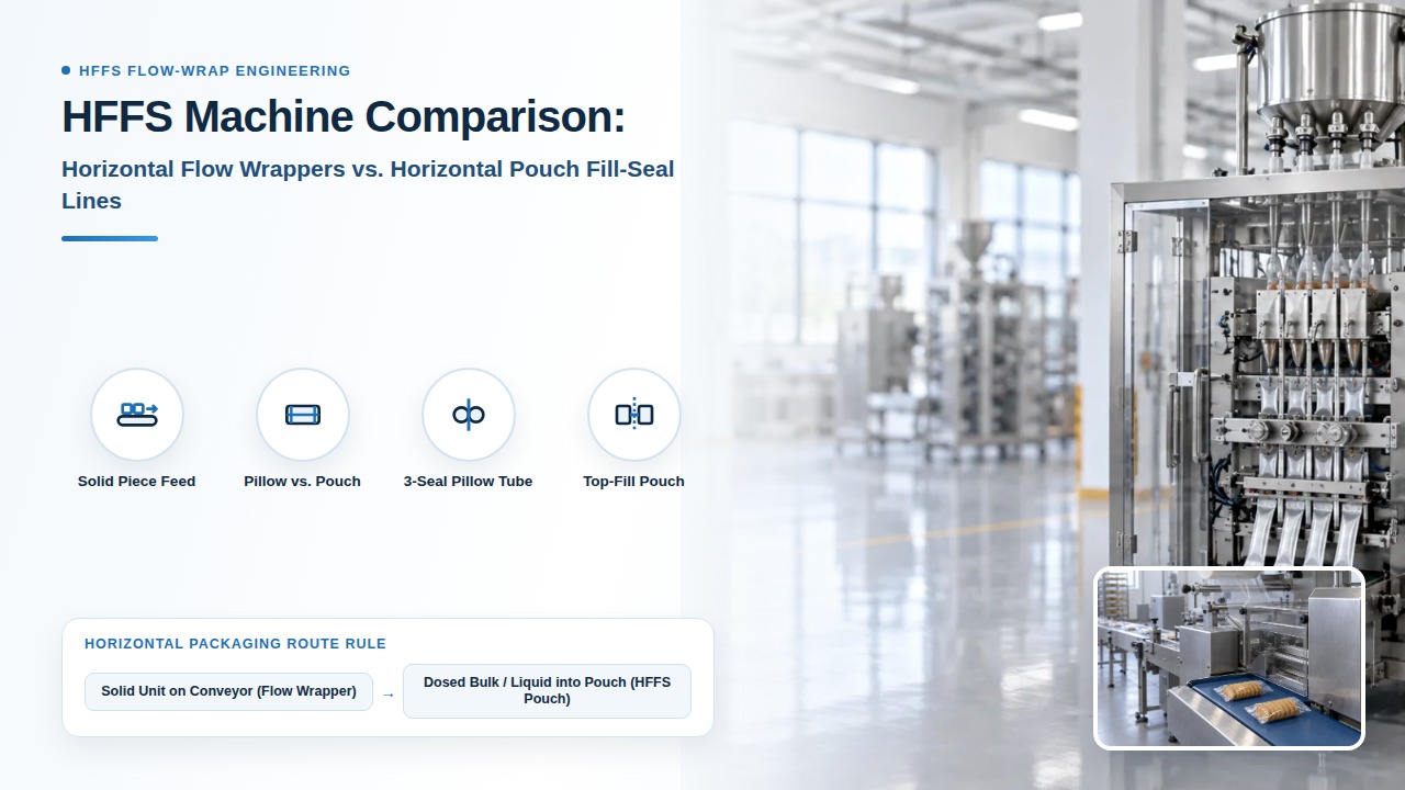
HFFS Machines: Choose the Right Horizontal Packaging Process
HFFS can refer to flow wrappers or horizontal pouch systems. Identify how your product enters the pack before comparing machine proposals.
Read more