
Updated 2026-10-17
Routing a heat-sensitive or high-speed single product through a hot-air shrink tunnel causes surface melting, 15% to 20% edge-trim film waste, and 10 to 24 kW of unnecessary continuous thermal load, whereas forcing an unstable multi-item bundle onto a standard wrapper without a tray leads to loose film collapse and cross-jaw jams. Evaluating flow wrap vs shrink wrap requires comparing four engineering boundaries: finished seam geometry (three-seal pillow pack vs perimeter bead weld plus thermal contraction), product heat exposure (localized millisecond jaw contact vs 3 to 8 seconds inside a 120 to 180 °C tunnel), film polymer mechanics (heat-set BOPP/barrier laminates vs biaxially oriented POF/PE shrink films), and single-lane output economics. While a horizontal flow wrapper (HFFS) forms, seals, and cuts a finished pillow pack around the product in one continuous pass without a heat tunnel, a shrink wrapping system encloses the product in a loose film bag first and relies on a separate recirculating hot-air tunnel to draw the film taut.
Engineering summary: Specify horizontal flow wrapping (HFFS) when your line requires 50 to 600+ packs/min continuous output, zero edge-trim film waste, hermetic or gas-flushed (MAP) barrier seals under ASTM F88, or zero ambient heat exposure on temperature-sensitive products; specify L-bar or continuous side-seal shrink wrapping (or a combined HFFS + shrink tunnel line) when the package requires 55% to 68% biaxial film recovery under ASTM D2732 to lock trayless multipacks together or create a glossy skin-tight retail overwrap.
| Engineering parameter | Horizontal Flow Wrapping (HFFS Baseline) | Shrink Wrapping (L-Bar / Side Sealer + Tunnel Baseline) |
|---|---|---|
| Process stages & equipment scope | Single-stage continuous forming box + rotary fin wheels + rotary or box-motion cross jaws (no shrink tunnel) | Two-stage system: L-bar sealer (e.g., ULMA SL 300) or side sealer (ULMA SC 200) + recirculating hot-air shrink tunnel (ULMA TR 100) |
| Finished seam geometry & venting | 1 longitudinal fin or lap seam (12–15 mm) + 2 serrated transverse end crimps (12–18 mm); hermetic or peelable (no vent holes) | 1 longitudinal side trim-seal + 2 hairline hot-knife bead seals (1–2 mm); requires mechanical micro-perforation pinholes to vent tunnel air |
| Film polymer & ASTM D2732 free shrink | Heat-set BOPP, BOPP/CPP, PET/PE, paper/PE, or cold-seal webs (20–65 um); <2% to 4% thermal shrinkage at 120 °C | Biaxially oriented polyolefin (POF, 12–25 um / 48–100 gauge) or LDPE bundling film (30–75 um); 55% to 68% free shrink at 120 °C |
| Product thermal exposure profile | 25–60 ms localized contact at fin/end seal flanges only (or 0 °C ambient pressure with cold-seal adhesive) | 3 to 8 s whole-package immersion inside a 120 to 180 °C recirculating hot-air tunnel chamber (e.g., 1,335 mm chamber on ULMA TR 100) |
| Baseline speed & connected electrical load | 50–170 packs/min standard rotary (up to 300–600+ packs/min high-speed); 3.0 to 5.0 kVA (2.5–4.2 kW) total draw | 15–35 packs/min (L-bar) or 50–125 packs/min (continuous side sealer); 10 to 26.6 kW combined draw (2.6 kW sealer + 9.2 to 24 kW tunnel) |
Process Boundary Comparison: Single-Stage HFFS Pillow Pack vs Two-Stage Sealer and Shrink Tunnel
The fundamental mechanical distinction between flow wrapping and shrink wrapping is how the film achieves its final fit around the product. In a horizontal flow wrapper—detailed in ULMA Packaging's Flow Pack HFFS reference and Syntegon's horizontal flow wrapper overview—a single flat web of dimensionally stable film folds over a forming shoulder tightly around the product cross-section. Counter-rotating fin wheels pull and weld the longitudinal seam while rotary or box-motion cross jaws crimp and sever the two ends. When the pack exits the cross jaws onto the discharge conveyor, the package is complete. For a full breakdown of the five internal machine zones, see how a flow wrapper works and our flow wrap packaging overview.
In a shrink wrapping line, sealing and tightening are separated into two distinct machines or modules:
- Stage A — Loose Envelope Forming & Perimeter Sealing: An intermittent angular L-bar sealer (
such as the ULMA SL 300 or ALF DQL5545D) or a continuous side sealer (such as the ULMA SC 200 or SC 500) feeds center-folded shrink film around the product. A PTFE-coated heated nichrome wire or hot knife welds the open side and ends, severing a25 to 50 mmcontinuous edge-trim selvage strip that winds onto a scrap take-up reel. Before entering the tunnel, needle wheels punch tiny air-evacuation pinholes along the film face. - Stage B — Convective Thermal Contraction (Shrink Tunnel): The loosely bagged item rides a silicone-roller or PTFE-mesh conveyor through an insulated hot-air shrink tunnel (
such as the ULMA TR 100 with a 1,335 mm chamber and 24 kW heater bank, or the compact 9.2 kW ALF DSB4522). Heated air circulating at120 to 180 °Cunlocks the biaxial orientation stresses frozen into the polyolefin (POF) or polyethylene (PE) film, shrinking the loose envelope by20% to 55%until it conforms tightly to the product contours while trapped air escapes through the pinholes. - Hybrid Route — Combined Flow Wrapper + Shrink Tunnel (
HFFS Shrink Bagging): For high-speed retail products that require a trim-free tight shrink finish (such as frozen pizzas, trayed produce, or multi-roll tissue packs), engineers pair a specialized polyolefin-capable flow wrapper directly ahead of a hot-air shrink tunnel (an architecture explicitly supported by ULMA's TR 100 shrink tunnel specification for Flow Pack HFFS lines). This hybrid configuration eliminates the12% to 20%edge-trim waste of an L-bar/side sealer while delivering a shrunk overwrap—at the cost of buying and powering both machines.
| Line architecture | Sealing & film transport mechanism | Baseline speed & electrical load | Dominant Failure Mode & Mechanical Prevention |
|---|---|---|---|
| Rotary HFFS Flow Wrapper (Pillow Pack, No Tunnel) | Flat rollstock folded in forming box; rotary fin wheels + 1-to-4-jaw rotary cross-sealing head (e.g., ULMA FR 100 / Syntegon Pack 202) | 50–300+ packs/min; 3.0–5.0 kVA (2.5–4.2 kW) electrical draw; 0% side-trim scrap | End-seal center-step channel leaks or product tail clipping -> Machine relief step in jaw serrations for the 4-layer fin intersection and enable optical Misplaced Product Detection (MPD) |
| Box-Motion HFFS Flow Wrapper (Hermetic / MAP) | Flat barrier rollstock; orbital long-dwell D-cam cross jaws providing 150–350 ms parallel seal dwell (e.g., ULMA FM 300) | 40–150 packs/min (up to 30 m/min web); 4.5–6.5 kVA draw + 6 bar gas/pneumatic supply | Residual oxygen drift or leakers on thick laminates (>50 um) -> Balance ASTM F1921 hot-tack window with stainless gas-flush lance and 180+ ms orbital dwell |
| Automatic L-Bar Sealer + Hot-Air Shrink Tunnel | Center-folded POF film; intermittent reciprocating L-frame hot knife (0.2–1.0 s dwell) + roller shrink tunnel (e.g., ULMA SL 300 + TR 100) | 15–35 packs/min; 10.0–26.6 kW total draw (0.8–2.6 kW sealer + 9.2–24 kW tunnel); 12–20% edge-trim scrap | Hairline bead-seal blowouts or dog-ear corner spikes in tunnel -> Calibrate pinwheel air-vent perforation density and match PTFE hot-knife wire tension to tunnel blower velocity |
| Continuous Side Sealer + Hot-Air Shrink Tunnel | Center-folded POF film; rotary continuous side-seal wheels + flying cross-seal bar + high-velocity shrink tunnel (e.g., ULMA SC 200 / SC 500) | 50–125 packs/min; 14.0–28.0 kW total draw; unlimited pack length capability | Side-seal selvage strip breaks or film balloons inside tunnel -> Maintain servo dancer tension on the trim wind-up reel and stage tunnel air louvers from bottom-to-top |
| Combined HFFS Flow Wrapper + Shrink Tunnel | Flat POF shrink rollstock formed on HFFS with trim-free lap/fin seal and pinholes, discharging directly into a shrink tunnel | 60–180 packs/min; 12.0–28.0 kW combined draw; 0% edge-trim waste | Longitudinal fin seam splits open under biaxial shrink tension in tunnel -> Specify cross-linked POF film with high hot-tack static lap seal or trimless side-blade HFFS head |
Seam Geometry, Film Polymer Mechanics, and Barrier Integrity (ASTM F88 vs ASTM D2732)
Inspecting a finished package reveals immediately which process created it—and whether that package can hold a protective atmosphere or survive distribution without a secondary carton.
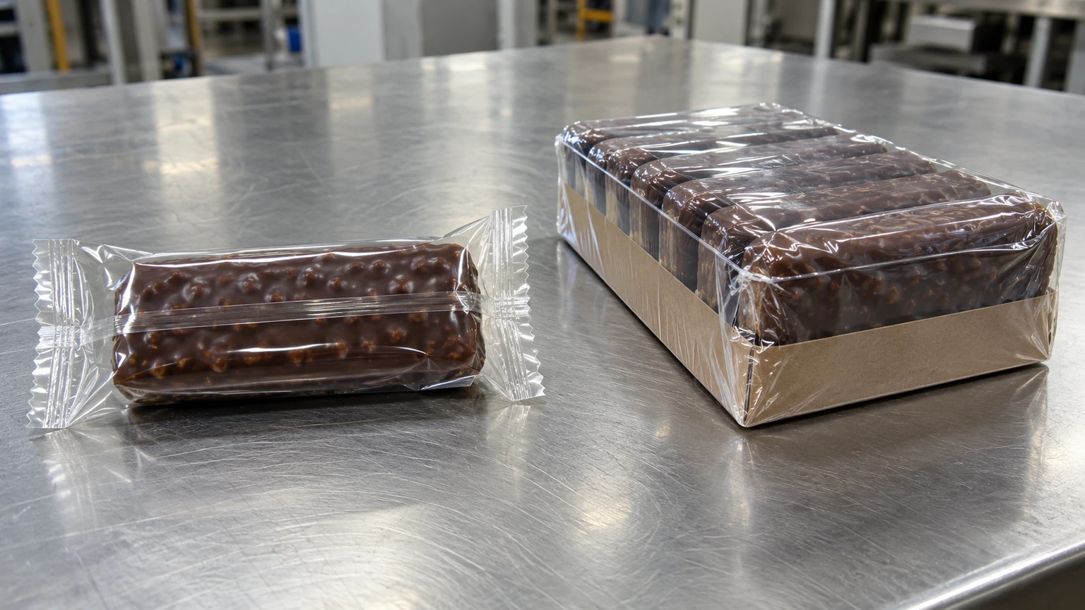
As established in Syntegon's engineering guide to horizontal flow wrapper sealing and cutting, a flow pack relies on surface-to-surface polymer fusion across wide serrated jaws (typically 12 to 18 mm wide at the ends and 12 to 15 mm on the longitudinal fin). Because the film web (coextruded BOPP, BOPP/CPP, PET/AL/PE, or cold-seal laminate) is heat-set during manufacturing so its unrestrained linear thermal shrinkage under ASTM D2732 is less than 2% to 4% at 120 °C, the printed graphics do not distort when passing the 115 to 165 °C fin wheels and cross jaws. More importantly, because no shrink tunnel is used, the film requires zero air-evacuation pinholes. That allows a flow pack to achieve verifiable hermetic peel and burst strength under ASTM F88 and ASTM F1921, supporting nitrogen flushing (MAP), moisture-sensitive bakery goods, and aroma barrier protection. Compare compatible laminates in our flow wrap film guide and HFFS vs VFFS comparison.
By contrast, shrink wrapping requires a film engineered with high biaxial orientation stress—most commonly 12 to 25 um (48 to 100 gauge) multi-layer coextruded polyolefin (POF) for retail packs or 35 to 75 um low-density polyethylene (LDPE) for heavy transit multipacks. Tested under ASTM D2732 (unrestrained linear thermal shrinkage in a constant-temperature bath), standard POF shrink films contract by 55% to 68% in both Machine Direction (MD) and Transverse Direction (TD) at 120 °C (reaching 65% to 75% at 130–150 °C). However, two structural constraints govern every L-bar or side-sealer shrink pack:
- Non-Hermetic Pinhole Venting: When a sealed bag enters a
140 to 170 °Cshrink tunnel, the air trapped inside expands rapidly while the film envelope shrinks by half. Without mechanical micro-perforations (pinholes), the pack inflates like a pillow and bursts at the seam. Because pinholes permanently vent the package to ambient air, standard shrink wrapping cannot hold a modified atmosphere (MAP) or protect hygroscopic biscuits/crackers from humidity unless the product is already sealed inside an inner primary pack or carton. - Hairline Bead-Weld Strength Limits: L-bar and side-seal hot knives sever and fuse the film simultaneously along a
1 to 2 mmmelted bead. While strong enough to withstand tunnel shrinkage and shelf handling, a bead weld lacks the calibrated12 to 18 mmpeelable or lock-seal flange required forASTM F88barrier certification. BothBOPP/CPPflow-wrap films andPOF/PEshrink films used in direct food contact must satisfyFDA 21 CFR 177.1520olefin polymer extractable limits.
| Film category | Typical thickness & ASTM D2732 shrink @ 120 °C | Seal mechanism & barrier capability | Dominant Failure Mode & Mechanical Prevention |
|---|---|---|---|
| Coextruded BOPP / BOPP-CPP laminate (Flow Wrap) | 20–45 um (80–180 gauge); <2–4% unrestrained shrink (dimensionally heat-set) | 12–18 mm serrated fin/crimp heat seal (115–165 °C) under ASTM F88; high moisture barrier, no pinholes | Jaw heat-through failure at 4-layer center fin fold -> Profile jaw serrations with center relief step and match dwell to film gauge |
| High-barrier PET/PE or EVOH laminate (MAP Flow Wrap) | 45–75 um; <2% thermal shrink; O2 transmission <1–5 cc/m²/day | Box-motion long-dwell hermetic heat seal (150–350 ms dwell); supports gas flushing (<1% residual O2) | Micro-channel leakers in end crimps during fast jaw opening -> Select sealant resin with high ASTM F1921 hot-tack strength |
| Pattern-applied cold-seal film (Heat-Sensitive Flow Wrap) | 22–40 um BOPP or metalized BOPP; 0% thermal shrink (ambient sealing) | Unheated serrated jaws bond cohesive latex adhesive on fin/end zones at 25–30 °C via contact pressure alone | Adhesive transfer or premature blocking on unwind rollers -> Use PTFE/silicone-coated guide rollers and pattern-registered adhesive margins |
| Biaxially oriented Polyolefin (POF Shrink Film) | 12, 15, 19, or 25 um (48, 60, 75, 100 gauge); 55%–68% balanced MD/TD free shrink at 120 °C | 1–2 mm hot-knife perimeter bead weld + 120–165 °C hot-air tunnel; high gloss, puncture-resistant, non-hermetic (pinholes) | Burn-through holes or fish-eye corner wrinkles in tunnel -> Switch to cross-linked POF for high-speed tunnels and balance MD/TD airflow louvers |
| Shrink bundling LDPE film (Transit Overwrap) | 35–80 um (140–320 gauge); 50%–70% MD / 15%–30% TD preferential shrink at 160–190 °C | Heavy-bar overlap weld or bullseye side open ends + high-velocity tunnel; unitizes bottle/can/carton multipacks | Film welds onto inner primary PE bags inside the tunnel -> Specify differential melt-point inner film or switch outer bundle to trayed HFFS |
Product Thermal Exposure and Mechanical Handling Boundaries
A product that survives localized jaw heat on a flow wrapper can be ruined inside a shrink tunnel. Engineers must evaluate thermal transfer and mechanical support separately before selecting a packaging route.
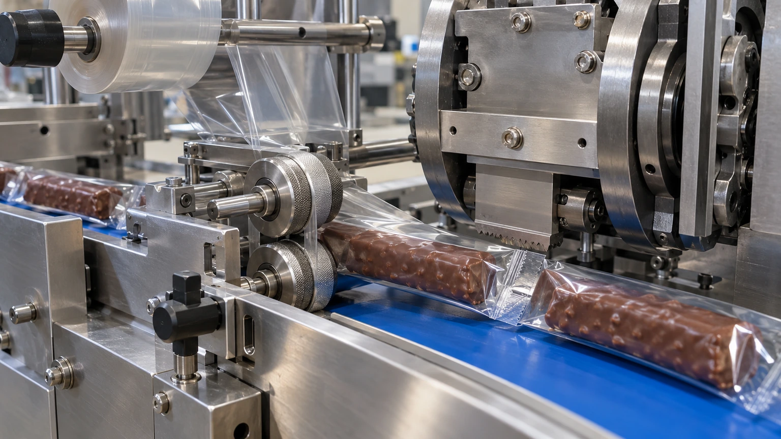
On a horizontal flow wrapper, the product body sits inside the cool center of the film tube at least 8 to 12 mm away from the longitudinal fin-seal nip and 8 to 12 mm clear of the transverse cross-sealing jaws (see flow wrapper sizing). Even on heat-seal machines running at 140 to 160 °C jaw setpoints, contact lasts only 25 to 60 ms at the film margins. For extreme thermal sensitivity—such as chocolate bars that bloom or melt above 30 to 32 °C (see chocolate bar packaging machines and cereal and protein bar flow wrappers)—switching to cold-seal film eliminates heaters entirely.
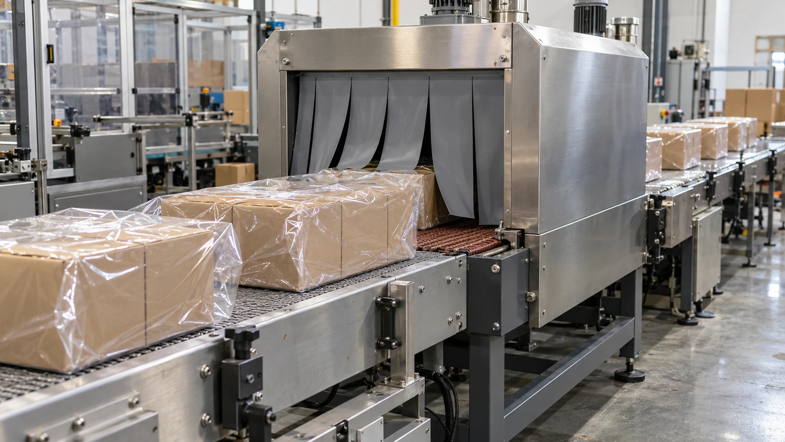
On a shrink wrapping line, the entire product and any primary packaging must travel through the 120 to 180 °C recirculating air stream of the shrink tunnel for 3 to 8 seconds. Furthermore, as the POF film shrinks, it exerts biaxial compressive force across all corners and edges. That creates three mechanical and thermal boundaries:
- Heat-Sensitive Foods, Pharmaceuticals & Direct-Thermal Labels: Chocolate coatings, gummy confections, frosted bakery items (
seebakery packaging machines), wax products, and direct-thermal barcode labels darken, melt, or deform during a5-secondtunnel pass at150 °C. - Flexible or Unsupported Thin Items: High-shrink
POFtension will bow or curl thin paperboard cards, unbacked booklets, or soft foam pads unless a low-shrink-force cross-linked film (12 to 15 um) is paired with precise tunnel airflow balancing. - Multi-Item Collation Stability: Neither a standard top-reel flow wrapper nor an L-bar sealer automatically stabilizes a loose stack of round or slippery items. On a flow wrapper, loose stacks require either a paperboard U-card/tray (
seecookie and biscuit flow wrapping and individual vs multipack cookie packaging) or a bottom-reel (inverted) belt feed where the film supports the group from underneath (seeflow wrapper types and manual vs automatic feeding). On a shrink wrapper, once the group survives the transfer across the seal bar into the tunnel, the shrinking film locks the bundle into a rigid self-supporting unit.
Physical-Threshold Engineering Rules: When to Specify Flow Wrap vs Shrink Wrap
Apply these four physical-threshold rules during early line engineering to select the correct packaging architecture before issuing supplier RFQs:
- Product Surface Melt & Thermal Sensitivity Threshold (
< 35 to 45 °C): If the product surface, coating, adhesive, or primary label degrades or melts at temperatures below35 to 45 °C(enrobed chocolate, probiotic nutrition bars, frosted pastries, candles, or direct-thermal shipping labels) -> prioritize horizontal flow wrapping (HFFS with heat-seal clearance or cold-seal jaws) over shrink wrapping because HFFS confines heat strictly to12 to 18 mmseal flanges for25 to 60 ms(or 0 °C with cold seal), whereas a shrink tunnel immerses the entire pack in120 to 170 °Cair for3 to 8 seconds. - Single-Lane Speed & Edge-Trim Scrap Threshold (
> 80 to 120 packs/min): If required single-lane throughput exceeds80 to 120 packs/minon discrete solid items or trayed multipacks -> prioritize continuous rotary HFFS flow wrapping over an L-bar (15 to 35 packs/min) or continuous side-sealer (50 to 125 packs/min) shrink system because rotary fin wheels and multi-jaw cross heads run up to150 to 600+ packs/minwithout reciprocating bar return strokes and eliminate the12% to 20%continuous side-trim selvage waste generated by center-folded shrink sealers. - Hermetic Barrier & Modified Atmosphere (MAP) Threshold (
< 1% to 2% Residual O2): If shelf-life specifications demand gas flushing (MAP), moisture/oxygen barrier protection, or verifiableASTM F88peel strength -> prioritize box-motion or rotary HFFS flow wrapping with barrier laminate film over L-bar/side-seal shrink wrapping because shrink film requires mechanical pinholes to vent expanding tunnel air, permanently venting the package headspace. - Contour Tightness & Trayless Bundle Unitization Threshold (
> 20% to 55% Free Shrink): If the finished package must pull drum-tight across irregular 3D contours without loose corner ears, or lock multiple cartons/jars into a rigid trayless unit -> prioritize polyolefin (POF) orLDPEshrink wrapping (or a combined HFFS + shrink tunnel line) using film rated at55% to 68%unrestrained thermal shrinkage underASTM D2732at120 °Cbecause standard heat-setBOPPflow-wrap film has< 3%thermal shrinkage and leaves flexible pillow gussets at both ends.
Quantitative Sizing, Trim-Scrap, and Thermal Energy Equations
To compare unit economics accurately, engineers calculate flat film consumption (including center-folded side-sealer trim waste), required shrink recovery, tunnel residence time, and electrical energy per 1,000 packs. For full HFFS web-width worksheets, see flow wrap film width and bag length sizing.
1. Flat Web Width and Edge-Trim Scrap Ratio (W_flow vs W_shrink_flat & R_trim)
W_flow = 2 * (W_prod + H_prod) + 2 * W_fin + C_forming
W_shrink_flat = 2 * (W_prod + H_prod + C_drape + W_trim)
R_trim (%) = ((2 * W_trim) / W_shrink_flat) * 100
- Variables:
W_prod= pack width (mm);H_prod= pack height (mm);W_fin= single HFFS fin-seal flange (12 to 15 mm);C_forming= HFFS forming-box clearance (10 to 16 mm);C_drape= L-bar/side-sealer clearance between product and side seal wire (25 to 40 mm);W_trim= selvage trim strip width per side (30 to 50 mmwound onto the scrap take-up reel). - Worked example: Wrapping a multipack tray of width
W_prod = 120 mmand heightH_prod = 45 mmon an HFFS flow wrapper (W_fin = 15 mm,C_forming = 14 mm) requiresW_flow = 2 * (120 + 45) + 2 * 15 + 14 = 330 + 30 + 14 = 374 mmflat web with0%edge-trim scrap. Wrapping the same120 x 45 mmtray on a center-folded side sealer (C_drape = 35 mm,W_trim = 40 mm) requires an unfolded web width ofW_shrink_flat = 2 * (120 + 45 + 35 + 40) = 480 mm(a 240 mm center-folded roll), generatingR_trim = (80 / 480) * 100 = 16.7%continuous edge-trim scrap wound onto the waste mandrel.
2. Required Shrink-Film Recovery (S_req) vs ASTM D2732 Free Shrink
S_req (%) = ((W_envelope - W_prod) / W_envelope) * 100
- Variables:
W_envelope= sealed film pouch width prior to entering the shrink tunnel (W_prod + H_prod * 0.5 + C_drape, mm);W_prod= finished product width (mm). - Worked example: When a
W_prod = 120 mmcarton enters the shrink tunnel inside a looseW_envelope = 155 mmfilm sleeve, the film must contract byS_req = ((155 - 120) / 155) * 100 = 22.6%restrained recovery—which requires specifying a biaxially orientedPOFfilm rated at55% to 65%unrestrained free shrink underASTM D2732at120 °Cso enough shrink force remains to pull corner dog-ears flat.
3. Shrink Tunnel Thermal Residence Time (t_tunnel)
t_tunnel (s) = (L_chamber / V_conv) * 60
- Variables:
L_chamber= heated shrink tunnel hood length (m);V_conv= tunnel roller conveyor speed (m/min). - Worked example: Conveying packs through a
L_chamber = 1.335 mtunnel (ULMA TR 100 baseline) atV_conv = 12.0 m/minimmerses the entire product in140 to 160 °Chot air fort_tunnel = (1.335 / 12.0) * 60 = 6.68 seconds(compared with 0.036 seconds [36 ms] of localized flange contact on a rotary HFFS flow wrapper).
4. Specific Electrical Energy per 1,000 Packs (E_1000) and Net Shift Output (Q_net)
E_1000 (kWh / 1,000 packs) = (P_avg * 1000) / (N_ppm * 60)
Q_net = N_ppm * 60 * T_shift * OEE_avail * (1 - R_scrap)
- Variables:
P_avg= average continuous electrical power draw (kW);N_ppm= line speed (packs/min);T_shift= shift duration (hours);OEE_avail= line availability;R_scrap= package reject fraction. - Worked example: An L-bar + shrink tunnel line drawing
P_avg = 14.5 kWaverage power (2.6 kW sealer + 11.9 kW tunnel duty load) atN_ppm = 25 packs/minconsumesE_1000 = (14.5 * 1000) / (25 * 60) = 9.67 kWh per 1,000 packsand yieldsQ_net = 25 * 60 * 8 * 0.82 * 0.99 = 9,742 good packs/shift, whereas a rotary HFFS flow wrapper drawingP_avg = 3.2 kWatN_ppm = 100 packs/minconsumesE_1000 = (3.2 * 1000) / (100 * 60) = 0.53 kWh per 1,000 packs(an 18.2x lower electrical energy cost per pack) and yieldsQ_net = 100 * 60 * 8 * 0.85 * 0.985 = 40,188 good packs/shift.
3-Year Energy, Film Scrap, and Downstream Case-Packing TCO Ledger
Comparing a standalone L-bar sealer quote against a horizontal flow wrapper quote without accounting for shrink-tunnel kWh draw, HVAC cooling load, side-trim waste, and downstream cartoning/case-packing handoff distorts three-year Total Cost of Ownership (TCO). Review machine capital budget tiers in flow wrapper price, solid hardware/household applications in non-food flow wrapping, bread closure comparisons in bread packaging machines and bread flow wrap vs bagging, and our downloadable flow wrapper requirements checklist.
| TCO cost category | Horizontal Flow Wrapper (HFFS) 3-Year Profile | L-Bar / Side Sealer + Shrink Tunnel 3-Year Profile | Engineering action during line specification |
|---|---|---|---|
| Electrical energy & plant HVAC heat load | 3.0–3.5 kW average draw (~12,800–14,000 kWh/yr across 4,000 hrs); negligible ambient heat rejection into cooled food packing rooms | 12.0–18.0 kW average draw (~48,000–72,000 kWh/yr across 4,000 hrs) + 3 to 5 tons of extra plant HVAC cooling load to remove tunnel exhaust heat | Calculate kWh per 1,000 packs (E_1000) and verify 3-phase feeder amperage (25–40 A required for tunnel alone) plus overhead hood extraction |
| Film edge-trim & startup scrap | 0% side-trim scrap (full flat web width forms the pillow tube); 0.8–1.5% reel-splice registration waste with servo eye-mark recovery | 12%–20% continuous edge-trim selvage wound onto scrap reels on center-folded L-bar and side-sealer lines + 3–5 packs lost if tunnel stops with packs inside | Compare net film weight per 1,000 packs including trim waste, or evaluate a trim-free HFFS + shrink tunnel hybrid if shrink finish is mandatory |
| Consumable wear parts & changeover downtime | Hardened rotary cross-jaw knives and cartridge heaters last 6–18 months; servo recipe recall switches bag length in 3–8 minutes | PTFE glass-cloth tapes, silicone rubber seal pads, and nichrome hot-knife wires require replacement every 1–4 weeks to prevent burn-through | Specify quick-change cartridge knives and OSHA 29 CFR 1910.212 / ISO 12100 interlocked guarding on both jaw and seal-bar assemblies |
| Downstream checkweighing, cartoning & case packing | Discharges uniform-pitch packs at 5–12% belt overdrive directly into inline checkweighers, metal detectors, top-load cartoners, or case packers | Packs exit the shrink tunnel hot (60–90 °C film surface) with soft tacky seals; requires a 1.5–2.5 m cooling fan conveyor before robotic pick-and-place or case packing | Budget floor space and cooling fans after any shrink tunnel so hot polyolefin film does not stick together inside shipping cases |
What to Send Us for a Flow-Wrap vs Shrink-Wrap Engineering Evaluation
| Item | Why we need it | Example format |
|---|---|---|
| Finished benchmark pack or target presentation photos | Identifies whether the target pack uses a 3-seal HFFS pillow fin/crimp or a center-folded perimeter bead seal with tunnel shrinkage | Front, back, end-crimp, and opened-wrapper photos showing longitudinal fin vs hairline bead weld and any air-vent pinholes |
| Product or multipack dimensions (L x W x H) & tray spec | Calculates flat web width (W_flow vs W_shrink_flat), edge-trim ratio, forming-box clearance, or tunnel aperture (e.g., 400 x 230 mm) | 180 x 120 x 45 mm corrugated tray holding 6 biscuits (210 g total), or 110 x 40 x 22 mm single coated bar |
| Maximum permissible product surface temperature (°C) | Determines whether the item can survive 3–8 s in a 120–170 °C shrink tunnel or requires HFFS heat-seal / cold-seal jaws | Dark chocolate coating melts above 31 °C (zero tunnel exposure allowed), or rigid cosmetic carton tolerates 150 °C for 5 s |
| Shelf-life, barrier & seal strength requirements | Establishes whether pinholed POF shrink film is acceptable or if hermetic ASTM F88 / MAP barrier laminate is mandatory | 9-month shelf life requiring <1.0% residual O2 nitrogen flush and >3.0 N/15 mm ASTM F88 peel strength (no pinholes) |
| Target throughput (packs/min), utilities & floor footprint | Matches speed against L-bar (15–35 ppm), side sealer (50–125 ppm), or rotary HFFS (50–300+ ppm) and checks 3-phase kVA capacity | 120 packs/min target, 400 V 3-phase power (max 8 kVA available), feeding inline checkweigher and case packer |
Send Product Photos & Dimensions on WhatsApp for a Flow-Wrap vs Shrink-Wrap Engineering Review
Does a standard horizontal flow wrapper use a heat tunnel to shrink the film?
No. A standard horizontal flow wrapper (HFFS) folds dimensionally stable film (such as heat-set BOPP or barrier laminates with <3% thermal shrinkage) over a forming box and seals the longitudinal fin and two serrated ends at the final bag size without a shrink tunnel. Only specialized hybrid HFFS lines configured for biaxially oriented polyolefin (POF) film and air-vent pinholes feed into a downstream hot-air shrink tunnel.
Can shrink wrapping provide a hermetic seal or Modified Atmosphere Packaging (MAP)?
Standard L-bar and side-seal shrink wrapping cannot hold a hermetic seal or modified gas atmosphere because the film must be mechanically micro-perforated with pinholes so trapped air can escape inside the 120–180 °C shrink tunnel without bursting the bag. Products requiring gas flushing (<1% residual oxygen), moisture barrier protection, or ASTM F88 hermetic peel seals require a rotary or box-motion HFFS flow wrapper using unperforated barrier film.
Why does L-bar and side-sealer shrink wrapping generate 12% to 20% edge-trim film waste while flow wrapping generates zero?
L-bar and continuous side sealers wrap products inside center-folded shrink film and use a heated side knife to weld the two open edges together outside the product width, severing a continuous 30 to 50 mm selvage strip that winds onto a scrap reel. A horizontal flow wrapper folds a flat film reel stripped to the exact package perimeter plus two 12–15 mm fin-seal flanges, incorporating 100% of the web width into the finished pillow pack.
How do electrical power consumption and speed compare between a flow wrapper and a shrink tunnel line?
A standard rotary servo flow wrapper operates at 50 to 300+ packs/min while drawing 3.0 to 5.0 kVA (~2.5 to 4.2 kW) because heat is confined to small fin wheels and cross jaws (`~0.5 kWh per 1,000 packs`). An L-bar sealer (15–35 packs/min) or continuous side sealer (50–125 packs/min) paired with a recirculating hot-air shrink tunnel requires 10 to 26.6 kW of connected 3-phase heating power (`~4 to 10 kWh per 1,000 packs`) plus additional plant HVAC capacity to exhaust tunnel heat.
Related guides
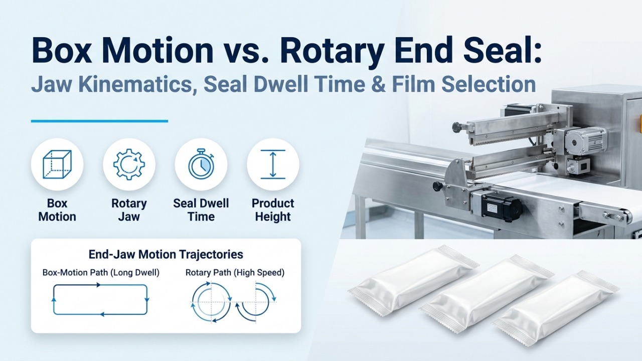
Compare Flow Wrapper Types and Configurations
Rotary or box motion? Top film or bottom film? Compare the feeding, film path and end-seal choices in a flow wrapper proposal.
Read more
Flow Wrapper Price: What Determines Your Project Cost?
What is included in a flow wrapper quote? Check feeding equipment, options, freight and installation before comparing prices.
Read more
Choosing Flow Wrap Film for Your Product and Machine
Choosing flow wrap film starts with the product and required seal. Gather the film specification, reel dimensions and samples for compatibility testing.
Read more