
Setting up flow wrapper date code placement and maintaining coder clearance seal jaw margins starts with matching the printer mounting point, registration trigger, and encoder speed tracking to the bag-forming and transverse sealing cycle. This guide supports the flow wrap packaging process guide and explains how date and lot coding units integrate with flat-web film transport, registration sensing, and rotary or box-motion end-seal stations.
On a horizontal flow wrapper, date and lot coding is applied while the film is still an open flat web upstream of the forming box, whereas transverse sealing and cutting take place downstream at the end-seal jaws after the product has entered the formed film tube.
Where Date Coders Sit on the Horizontal Flow Wrapper Film Path
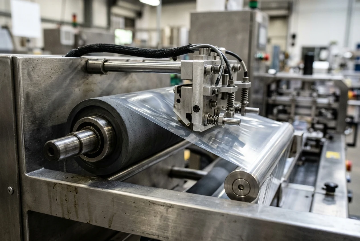
In a horizontal flow wrapper, packaging film unwinds from the backstand, passes over idler and tension-dancing rollers through the date-coder station and registration photocell, folds around the forming shoulder into a tube around the infeed product, passes through the longitudinal fin-seal wheels, and finally reaches the transverse end-seal jaws and cut-off knife.
Videojet states that while codes such as best-by dates can be applied after flow wrapping, it is much more practical to apply codes and variable brand information to the film before it enters the flow wrapper to ensure better quality printing and more readable codes. Videojet states that thermal transfer overprinters (TTO) print clear codes on glossy plastic and metallized flow wrap films with characters up to 12.7mm tall at speeds of up to 100 meters per minute.
Thermal Transfer Solutions states that on vertical form fill and seal machines loaded with a roll of pre-printed or plain packaging film, the in-line coder prints variable information onto the material whilst it is still in a flat position before the machine starts to form a funnel in which the product is filled. Thermal Transfer Solutions states that on horizontal flow wrapper machines, the product passes on a conveyor belt through the flow wrapper which automatically wraps the packaging material around the product and seals the packet ends, and the in-line coder is located in an area where the packaging film is still flat.
The XtraVac-450A film threading procedure numbers the machine stations as (1) packaging film, (2) photocell, (3) forming box, (4) pusher, (5) product, (6) fin seal roller, (7) end seal jaws and cut-off knife, and (8) discharging conveyor. The XtraVac-450A operation manual states that heating takes 20-30 minutes to rise up to the setting value across four separately adjustable heating elements, with general temperature suggestions of 120℃ for plastic material, 150℃ for paper material, 180℃ for aluminum foil material, and 100˚C for the coder.
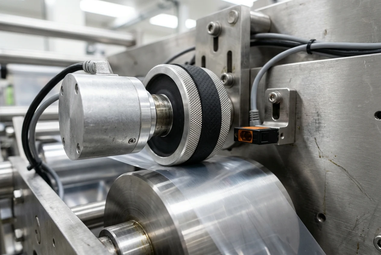
Opendate states that intermittent motion thermal transfer printers print onto a web or label that stops once per machine cycle during the stop time, whereas on a flow wrapper the film moves continuously while the machine is operating, requiring a continuous printer adapted to print onto a continuously moving substrate. Opendate states that continuous Thermocode thermal transfer printers use an encoder device to measure the speed of the moving substrate and calculate how fast to lay down the print image and feed the thermal ribbon, ensuring consistency of print quality and position whether the substrate is accelerating from start up, decelerating to a stop, or running at a constant speed.
Linx Printing Technologies reports that film tension, stretching and sealing during packaging can distort or misalign printed codes. Linx Printing Technologies states that heat-based marking methods or incorrectly specified laser settings can deform, melt, or weaken thin plastic films, and downstream sealing, shrinking or handling can damage or degrade codes if inks are not sufficiently durable. Linx states that reliable drying performance is critical on flow wrap lines where film passes immediately over rollers and guides after coding, and fast-drying inks help prevent smudging and code transfer.
Linx developed its 1061 ultra-strong plastic-adherent ink for Linx 9000 Series CIJ printers to pass tough tape tests on low surface energy plastics such as PP and PE, resist rubbing and abrasion, and resist thin oil contamination on food packaging. The Linx UVG5 UV laser codes flexible plastics at up to 2000 characters/second and line speeds up to 600m/min with an IP65 option, delivering permanent coding that cannot be removed or smudged with reduced thermal stress applied to the packaging.
The Linx TTO Series is suitable for intermittent and continuous lines, offers a choice of 32mm, 53mm or 107mm wide printheads, is instantly dry for durable codes, and has black and coloured ribbons available for high-contrast. According to Packaging Europe, the Videojet 6230 TTO thermal transfer overprinter features an airless printhead that eliminates the need for compressed air and a cassette design with a 700m ribbon length typically much longer than hot-stamp ribbons, and requires fewer ribbon changes versus other competitive systems.
| Web Path Station | Film Geometry and Support | Suitability for Date Coding | Primary Mechanical Constraint |
|---|---|---|---|
| Unwind frame before registration eye-mark sensor | Open flat web supported over idler and backing rollers | Primary mounting zone for thermal transfer overprinters and continuous inkjet brackets | Requires dedicated backing roller support and stable web tension across idler rollers |
| Flat web between registration eye-mark sensor and forming shoulder | Open flat web under dancing-roller tension control | Suitable for flat-web inline coding upstream of the forming box | Fast-drying inks required where film passes immediately over rollers and guides after coding |
| Forming box and longitudinal fin-seal deck | Film folding into a tube around moving product | Not suitable for flat-web contact printing once folding starts | Film tension, folding geometry, and fin-seal rollers distort or smudge wet codes |
| Rotary or box-motion transverse end-seal station | Closed film tube compressed between heated serrated jaws | Not used for printhead mounting; acts as the downstream thermal clearance boundary | Jaw heat, crimping pressure, and cyclic web deceleration |
TTO vs Inkjet Integration: Continuous and Intermittent Motion Regimes
Selecting a thermal transfer overprinter flow wrapper integration or a non-contact continuous inkjet setup depends on whether the film web moves continuously or dwells intermittently, how fast the substrate accelerates, and what barcode or alphanumeric print area the pack layout demands.
According to Table 1–1 of the Markem SmartDate 3 manual, the intermittent SmartDate3i has a print area of 2.1 ” x 2.9 ” (53 mm x 74 mm), variable print speed up to 39.0 inch/sec (1 m/sec), and 300 dpi (12 dots/mm) printhead resolution. According to Table 1–1 of the Markem SmartDate 3 manual, the intermittent SmartDate3i requires a 6 bar/90 psi maximum dry uncontaminated air supply, with air consumption of 2.5 ml/cycle maximum at 5 bar with a 4 mm (0.16 ”) printhead gap and 0.6 ml/cycle typically at 3 bar with a 1.5 mm (0.06 “) printhead gap.
According to Table 1–2 of the Markem SmartDate 3 manual, the continuous SmartDate3c has a print area of 2.1 ” x 3.9 ” (53 mm x 100 mm), variable print speed up to 59.05 inch/sec (1.5m/sec), and 300 dpi (12 dots/mm) printhead resolution. According to Table 1–2 of the Markem SmartDate 3 manual, the continuous SmartDate3c requires a 6 bar/90psi maximum dry uncontaminated air supply, and without APS its air consumption is 2.5 ml/cycle maximum at 5 bar with a 4 mm (0.16 ”) printhead gap and 0.6 ml/cycle typically at 3 bar with a 1.5 mm (0.06 “) printhead gap. According to Table 1–2 of the Markem SmartDate 3 manual, with APS enabled on the continuous SmartDate3c, air consumption is 8.8 ml/cycle maximum at 5 bar with a 4.0 mm printhead gap and 2.0 ml/cycle typically at 3 bar with a 1.5 mm (0.06 “) printhead gap.
The Markem SmartDate3 cassette-loaded ribbon specification supports a maximum ribbon length of 900 metres (2,952 ft), a maximum ribbon width of 55 mm (2.2 ”), and a minimum ribbon width of 20 mm (0.8 ”). Each Markem SmartDate3 thermal printhead has 12 ceramic-glazed heating elements (printing dots) per mm along the print line, and its stepper motors for printhead/shuttle motion and ribbon feed rotate so that linear motion is equivalent to 12 steps per mm.
The Markem SmartDate3i intermittent version prints onto stationary packaging material during the machine dwell time within a 53 mm width by 74 mm length print area against a flat print platen. The Markem SmartDate3i intermittent operating sequence is: 1. a Print Go signal triggers the print delay timer, 2. the print delay elapses and the printhead moves into position, 3. the printhead moves along a linear slide and prints, 4. the printhead retracts, and 5. the printhead returns to its home position and the ribbon moves along ready for the next print.
The continuous version of the Markem SmartDate3 is designed to print whilst on continuous running substrate and features the Advanced Print System facility (APS), which increases print speed by 50% from 1 m/s to 1.5 m/s of printing. Because the Markem SmartDate3c prints onto moving materials over a print roller within a 53 mm width by 100 mm length print area and matches print speed to substrate speed using a speed monitoring encoder, Markem states it is the ideal coder for continuous motion form fill and seal machines and horizontal flow wrappers.
The Markem SmartDate3c continuous operating sequence is: 1. a Print Go signal triggers the Debounce Encoder distance, 2. the Encoder distance elapses and the printhead moves into position, 3. the stationary printhead prints while a ribbon shuttle in the Printer Cassette matches ribbon speed to the substrate, and 4. the printhead retracts and the shuttle returns to its home position. TTOParts reports that on continuous application printers such as the Videojet Dataflex 6530 and 6330, the film moves continuously without stopping and the printhead does not traverse horizontally across the carriage, moving only up and down to contact the substrate when a print signal is received.
Markem SmartDate3 Non-Ribbon Save modes support speeds of up to 600 mm/sec in Normal mode, up to 1000 mm/sec in High speed mode, and up to 1500 mm/sec in APS Varying Ratio mode. For Markem SmartDate3c APS mode, Markem recommends a Print Gap of 0.5 mm - 1.0 mm, Head Out Time of 25 ms, Print Darkness of 100%, Air Pressure of 2.0 - 2.5 bar maximum, and the default Brake Timer of minus 20 ms.
| Coder Technology | Web Contact and Backing | Motion Synchronization Method | Seal-Jaw Clearance and Smudge Considerations |
|---|---|---|---|
| Continuous-motion thermal transfer overprinter | Contact nip between printhead, ribbon, film, and rotating print roller | Rotary encoder wheel riding on the moving film web | Instantly dry thermal ribbon transfer avoids roller smudge upstream of the forming box |
| Intermittent-motion thermal transfer overprinter | Contact stroke across a flat platen while the local film span is stationary | Print trigger during web dwell | Requires complete web dwell during print stroke to avoid elongated characters |
| Non-contact continuous inkjet and laser marking | Air gap over a low-vibration film span supported beside an idler roller | Registration trigger plus encoder pulse stream scaling character timing | Fast-drying inks help prevent roller smudge; Linx UVG5 marking applies reduced thermal stress |
| Integrated heated coder on the film carriage | Heated coding head contacting the film web upstream of the forming box | Mechanical phase coupling or PLC print-position trigger | Mounted upstream on the flat film path clear of the fin-seal and end-seal stations |
Trigger Timing, Registration EyeMarks, and Encoder Synchronization
Achieving repeatable flow wrap date code position requires synchronizing three signals: the registration photocell pulse that detects each printed eye-mark on the film, the print-position delay offset that phases the code into the target panel of the bag repeat, and the rotary encoder pulse train that matches printhead firing speed to instantaneous web velocity. For how jaw dwell time and temperature shape the seals that the printed code must clear, see the crimp dwell time and seal strength guide.
Markem SmartDate3 installation requires 115/230 V AC (+10%, -15%) 50/60 Hz, 300 VA (max.) or 100/200 power, 6 Bar (max.) dry uncontaminated compressed air, a Print Go signal from a closing volt-free contact or a positive-edge-triggered 24 V DC PNP sensor, and on SmartDate3c an encoder to monitor substrate speed. Markem recommends setting air pressure at 3.5 to 4.5 bar for SmartDate3i Standard operation, 3.5 to 4.5 bar for SmartDate3c Standard operation, and 2 to 2.5 bar for SmartDate3c with APS enabled, cautioning that excessive air pressure on installation may over-stress and prematurely damage the printhead.
For continuous printing on the Markem SmartDate3c, the encoder must provide 3 pulses per mm of substrate travel via an NPN open collector output operating at 24 V DC—typically a 500 pulses per rev. encoder with a 53.05 mm tracking wheel—and must measure substrate speed at the point of printing, preferably on the actual substrate. Markem specifies positioning the print platen or roller so that the product is presented at a maximum distance of 1.00 mm to 1.5 mm for SmartDate3i and 0.5 mm to 1.00 mm for SmartDate3c from the printhead when in the set position (for example with the cassette fully locked or the printhead in the home position).
On the Markem SmartDate3 15-way female Control I/O connector, a voltage-free Print Go contact wires between terminals 1 (24 V DC) and 2 (PRINT GO), whereas a PNP sensor wires Signal to terminal 2 (PRINT GO), Ground to terminal 3 (GND), and Power to terminal 1 (+24 V), drawing a maximum of 13 mA at 25 VDC. Markem SmartDate3 ribbon supply clutch calibration sets 20mm to 35mm x 600/900m ribbons to the Middle of Zone 1 (500/550gms) and 40mm (and above) x 600/900m ribbons to the Middle of Zone 2 (1000/1050gms).
On the Markem SmartDate3, Debounce Time avoids double triggering on noisy PRINT GO signals and is sampled every 5 milliseconds (so a 10 milliseconds setting requires a Print Signal of at least 15 milliseconds), and Markem advises setting debounce time to zero where possible on SmartDate3c continuous printers because a time delay in the cycle may produce print drift. On Markem SmartDate3i intermittent printers, Print Delay sets a delay between a valid PRINT GO signal and when the printhead moves out into position, allowing time for the substrate to settle if PRINT GO is received before the substrate is stationary.
Markem SmartDate3 Head Out time (default 20ms, reducible as a last resort to 15ms) coordinates printhead movement with ribbon acceleration so the head reaches the substrate just as ribbon and substrate speeds match; if Head Out is too short the first part of the print is cut off, and if too long the head moves before ribbon acceleration, causing ribbon breaking or scuffing prints. On the Markem SmartDate3, Start Border and End Border insert blank lines (steps) where 1 line = 0.083mm or 0.0033” before and after printing without wasting ribbon, default Print speed is 200mm/s, and default Head In retraction time is 3ms.
When the host packaging machine stops during a print cycle, the Markem SmartDate3c Abort Print Mode offers Auto (lifts printhead and returns ribbon shuttle home after Abort Print Delay, aborting the print), Hold Print (lifts printhead while keeping the shuttle in position so printing resumes when the substrate moves, which may leave a small part missing), and Hold Reprint (reprints the whole image at a slightly different position upon restart). On the Markem SmartDate3i intermittent printer, Print Time (Head Out + Start Border + Print + End Border + Head In) MUST be less than the host machine dwell time (with exponential acceleration taking 7mm to accelerate to 500mm/s), whereas on the continuous SmartDate3c the critical timing limit is Repeat Time.
Markem SmartDate3 speed logging records 4000 lines (encoder pulses) showing substrate speed and print signal state, and any Move X offset (> 0) delays the actual start of print by the offset multiplied by 3 because there are 3 encoder pulses per mm. The XtraVac Flow Wrapper 450A manual requires keeping the photo registration (eye mark) position within a tolerance of ±5mm, noting that the photo registration mark position is subjected to the bag length.
In the Siemens SIMATIC Rotary Knife application (Entry ID 109757260, V1.5.0), Angle start of cut (StartSyncAngle [°]) and Angle end of cut (EndSyncAngle [°]) define the synchronous sector around 0° where the cutting knife must move in synchronism with the material, and DistanceToSensor [mm] defines the distance between the cut position (0°) and the sensor used for material and print mark detection. In the Siemens SIMATIC Rotary Knife application, when print mark correction is started in Automatic mode, the basic deviation cutPositionCorrectionBasicCorrectionValue can be at most ± half of the format length, the position deviation of the print marks to the set format length is stored in addition to the previous deviation in the cutPositionBuffer, and correction is only started when cutCorrWait = 0 (how many cuts are waited until the first detected print mark with activated print mark correction is in front of the rotary knife).
Siemens SIMATIC Rotary Knife print mark correction limits require switching off print mark correction when changing formats until the desired format is cut, state that a deviation greater than half the format length is not possible, and require the distance to sensor to be at least the longest possible format length. To control the headcut length in the Siemens SIMATIC Rotary Knife application, the operator sets distanceToSensor (the distance between the 0° cut position and the sensor) and firstCutCorrection with quickStart = FALSE, homes the material axis to 0mm at the sensor in Manual mode, and changes from Startpos to Automatic so the material passes the distance of distanceToSensor + firstCutCorrection before the cut.
Siemens SIMATIC Rotary Knife documentation states that cut-length inaccuracies at machine acceleration (formats too large) and deceleration (formats too small) occur when the measuring wheel lifts or slips on accelerated material or when changes in material tension cause stretching or compression. The ABB AN00253 Rotary Knife PLCopen application note configures its example system with a 131072 counts per rev knife motor encoder, 100mm knife diameter, 10:1 motor-to-roll gear ratio, and a 20000 counts per rev quadrature material encoder driven directly from a 50mm diameter roll.
Protecting Seal-Jaw Clearance and Troubleshooting Drift or Smudge
Even when the printhead is mounted upstream on the flat web, an improperly phased trigger, an excessive Move X/Y offset, or a slipping encoder can allow the printed date code to drift into the downstream longitudinal fin-seal wheels or the heated transverse end-seal jaws. When evaluating how jaw geometry and dwell time interact with film sealing windows, compare film width and bag length sizing and the high-speed flow wrapper machine hub.
TTOParts found that on continuous printers, accumulation of dust and debris over time can cause the linear slide to slip subtly during printing, triggering a printhead carriage position error even when the printhead and motor are not faulty. To prevent the Videojet Printhead Carriage Position Error on Dataflex 6530 or 6330 printers, TTOParts specifies maintaining the printhead gap within the 1-5mm range and aligning the print position over the roller away from extremes in both directions.
On the Markem SmartDate3, the Move Y parameter adjusts the print position across the 53 mm wide printhead; moving a 40 mm wide image across the printhead by 20 mm gives a 60mm total width, so the 53 mm printhead prints only the first 33 mm and leaves off 7mm. On the Markem SmartDate3i, the Move X parameter moves the print image down the print area; moving a 40mm long image down by 40mm gives an 80mm total length that exceeds the 74mm maximum print height, missing the last 6mm and triggering WARNING, IMAGE HEIGHT + BORDERS + OFFSET EXCEEDS MAXIMUM PRINT AREA.
On the Markem SmartDate3, increasing Darkness% above the standard 100% up to the 140% maximum darkens printing for high print speeds, but excessive darkness increases smudging and may contribute to poor print quality or ribbon breakage, especially when printing barcodes or horizontal lines. Markem SmartDate3 troubleshooting states that elongated or compressed print occurs on SmartDate3i when the printhead prints while the substrate is still moving (requiring Print Delay modification) and on SmartDate3c when Match Substrate is set to No or the encoder is slipping. Markem SmartDate3 troubleshooting states that prints occurring only on every other product (or less) happen when the overall print cycle is longer than the product-to-product time, including on SmartDate3c when the Move X parameter is set too long.
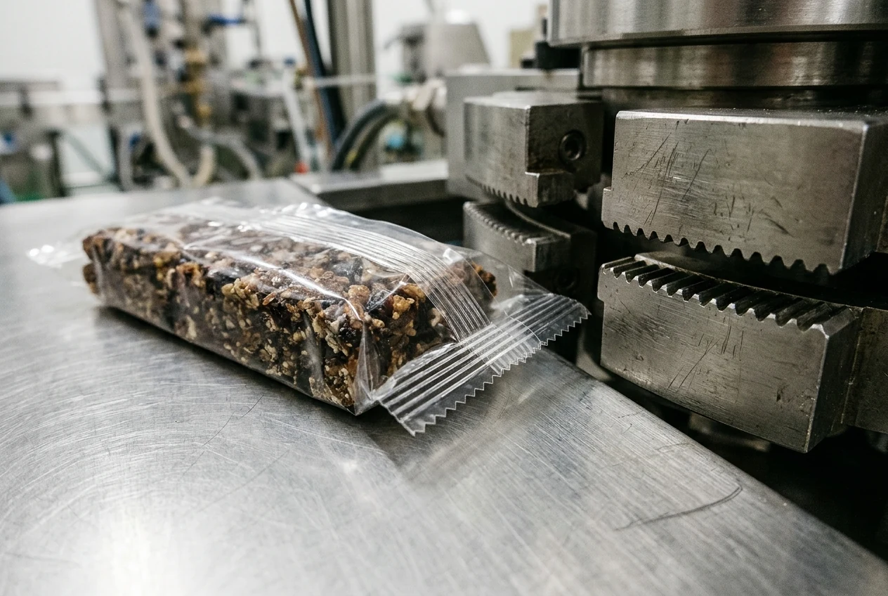
On the XtraVac Flow Wrapper 450A, the center height of the end seal clearance is adjusted by the s screw bar to h= product height x 1/2, and the upper and lower end sealing jaws must be aligned before installing the knife and anvil so the sealing faces just make contact with minimal interference. Greener Corporation's Fin Seal Relief integrates a relief into the crimper serrations positioned to the fin seal location—where the film layers are doubled—allowing for some variance in film tracking while maintaining full contact and consistent pressure distribution over the rest of the end seal, while FRED (Fracture Elimination Design) alleviates pressure on the leading edge of the seal by absorbing force outside of the package width.
Greener Corporation states that the product, forming box, fin wheels, and the sealing and cutting head should all align on the same centerline, and product that is too far forward or back in the film tube can be damaged by the crimpers and contaminate the end seal. Greener Corporation states that fin folder wheels or another folding mechanism must consistently fold the fin seal so that it will lie flat against the package, because irregularities create wrinkles and creases in the fin seal that degrade package appearance and cause leakers at the end seal.
Greener Corporation explains that flexible packaging material tension is adjusted by the final dance roller entry angle into the forming box: a lower angle creates less tension and tightens the wrap, insufficient tension causes tracking problems, uneven fin seals, and end seal wrinkles, and excessive tension causes loosely wrapped packages, fin-seal stretch marks or wrinkles, and narrow undersized fin seals that pull out of the fin wheels. PacMatix notes that a weak front end seal while the back seal remains perfect on a flow wrapper is in almost every case due to an over-adjusted knife whose excessive pressure causes the jaws to flex or open slightly after cutting.
| Observed Pack Defect | Root Cause Along the Film Path | Diagnostic Check | Corrective Adjustment |
|---|---|---|---|
| Date code lands inside or across the transverse end-seal crimp | Print Delay, Move X offset, or registration offset is misadjusted | Inspect where the code sits relative to the eye-mark and transverse cut on a slow jog test pack | Adjust the print-position offset or coder Move X delay until the code centers in the clear window |
| Code position wanders forward and backward during speed ramps | Encoder wheel slipping on accelerated film or excessive debounce delay causing print drift | Check encoder tracking wheel contact pressure against its backing roller and verify debounce settings | Seat the encoder wheel firmly on the substrate and set continuous debounce delay to zero where possible |
| Printed characters look compressed, stretched, or cut off at the leading edge | Substrate moving during an intermittent print stroke, encoder slipping, or Head Out time misadjusted | Check whether Match Substrate is enabled on continuous coders and inspect Head Out timing | Modify intermittent Print Delay, enable substrate speed matching, or restore normal Head Out timing |
| Prints appear only on every other pack or clip at the printhead edge | Total print cycle plus Move X offset exceeds the pack-to-pack repeat time, or Move Y shifts image past printhead width | Compare total print cycle time against bag repeat period and verify Move X and Move Y offsets | Reduce Move X offset or mechanically reposition the printhead bracket instead of over-shifting in software |
Pre-Purchase Audit: Specifying Your Date-Coding Window
Before finalizing a machine quotation or ordering pre-printed registered film, packaging engineers should lock down the cutoff length, candidate web width, fin-seal allowance, and crimper width so the date-coding window has verified clearance from every heat-seal seam. To confirm the cutoff length and jaw pitch that set the bag repeat, review the 1-up vs 2-up jaw pitch and cutoff length guide and our Flow Wrapper Requirements Checklist.
Syntegon's Guide to Flow Wrapping gives the starting formula for determining cutoff length as Product Height divided by 0.86603 + Total Crimper Width + Total Product Length, where Product Height divided by 0.86603 determines the amount of film taken up by the angle to the end seal. Syntegon's Guide to Flow Wrapping gives the formula for sizing film web width as 2 x (Product Width + Product Height + Fin Seal Roller Height + 5mm), where common fin sealing roller heights of 6, 9 and 15 millimeter together with 5mm (0.2”) of film for tracking result in finseal widths of 11, 14 and 20 millimeters respectively.
Our Film Width and Bag Length guide defines rectangular perimeter P (mm) = 2 × [product width W (mm) + total height H (mm)], candidate web width = P + seam material + forming allowance, and complete cut repeats = round down [usable reel length (m) × 1,000 / cut pitch (mm)].
Prepare Your Film Dieline and Coding Specification for Review
When you are ready to verify coder bracket geometry, registration offset range, and seal-jaw clearance for your product, prepare the following project details:
- Film dieline and registration layout: flat film width, bag pitch (cut length), eye-mark dimensions and track location, and the exact longitudinal and lateral position of the date-code window relative to the transverse seal and fin seal.
- Line speed and motion profile: target packs per minute, linear web speed, and whether the wrapper runs continuous motion or intermittent dwell cycles.
- Coding format and substrate: number of print lines, character height, barcode requirements, and outer film layer composition.
- Interlock and utility preferences: airless electric versus pneumatic printhead actuation, plus Print Go sensor type and encoder wheel mounting space on the unwind frame.
Message LINEVO on WhatsApp to review your film dieline and date-coder integration requirements.
Frequently Asked Questions
Why do horizontal flow wrappers mount the date coder on the flat film web instead of next to the end-seal jaws?
Thermal Transfer Solutions states that on horizontal flow wrapper machines, the product passes on a conveyor belt through the flow wrapper which automatically wraps the packaging material around the product and seals the packet ends, and the in-line coder is located in an area where the packaging film is still flat.
What is the difference between continuous and intermittent TTO printing on a flow wrapper?
Opendate states that intermittent motion thermal transfer printers print onto a web or label that stops once per machine cycle during the stop time, whereas on a flow wrapper the film moves continuously while the machine is operating, requiring a continuous printer adapted to print onto a continuously moving substrate.
What encoder specification is required for continuous printing on a Markem SmartDate3c?
For continuous printing on the Markem SmartDate3c, the encoder must provide 3 pulses per mm of substrate travel via an NPN open collector output operating at 24 V DC—typically a 500 pulses per rev. encoder with a 53.05 mm tracking wheel—and must measure substrate speed at the point of printing, preferably on the actual substrate.
What causes elongated or compressed date codes on a thermal transfer overprinter?
Markem SmartDate3 troubleshooting states that elongated or compressed print occurs on SmartDate3i when the printhead prints while the substrate is still moving (requiring Print Delay modification) and on SmartDate3c when Match Substrate is set to No or the encoder is slipping.
What eye-mark registration tolerance is specified on the XtraVac-450A horizontal flow wrapper?
The XtraVac Flow Wrapper 450A manual requires keeping the photo registration (eye mark) position within a tolerance of ±5mm, noting that the photo registration mark position is subjected to the bag length.
Sources
- Videojet Technologies — Coding and Marking on Flow Wrapping Equipment Application Note
- Thermal Transfer Solutions — Guide to Coding on Flow Wrappers and Form Fill Seal Machines
- Linx Printing Technologies — Coding onto Plastic Film and Flexible Packaging Technical Guides
- XtraVac Packaging Machines — Horizontal Flow Wrapper Operation Manual
- Opendate Equipment — Continuous versus Intermittent Thermal Transfer Printing Guide
- Markem Corporation — SmartDate Thermal Transfer Overprinter Operation and Maintenance Manual
- TTOParts — Continuous Thermal Transfer Printhead Carriage Troubleshooting Technical Note
- Siemens AG — SIMATIC Rotary Knife Motion Control Application Description
- ABB Motion — Rotary Knife Control PLCopen Application Note
- Greener Corporation — Horizontal Flow Wrapper Crimper, Fin Seal, and Web Tension Technical Guides
- Syntegon Technology — Guide to Horizontal Flow Wrapping Film and Cutoff Sizing
- PacMatix — Horizontal Flow Wrapper End-Seal and Knife Setup Guide
- Packaging Europe — Airless Thermal Transfer Overprinter Technical Report
- FlowWrapper — Film Width and Bag Length Sizing Guide
Related guides
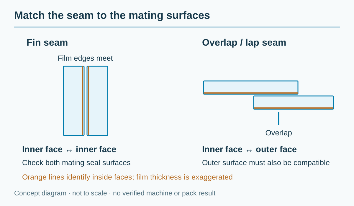
Choosing Flow Wrap Film for Your Product and Machine
Choosing flow wrap film starts with the product and required seal. Gather the film specification, reel dimensions and samples for compatibility testing.
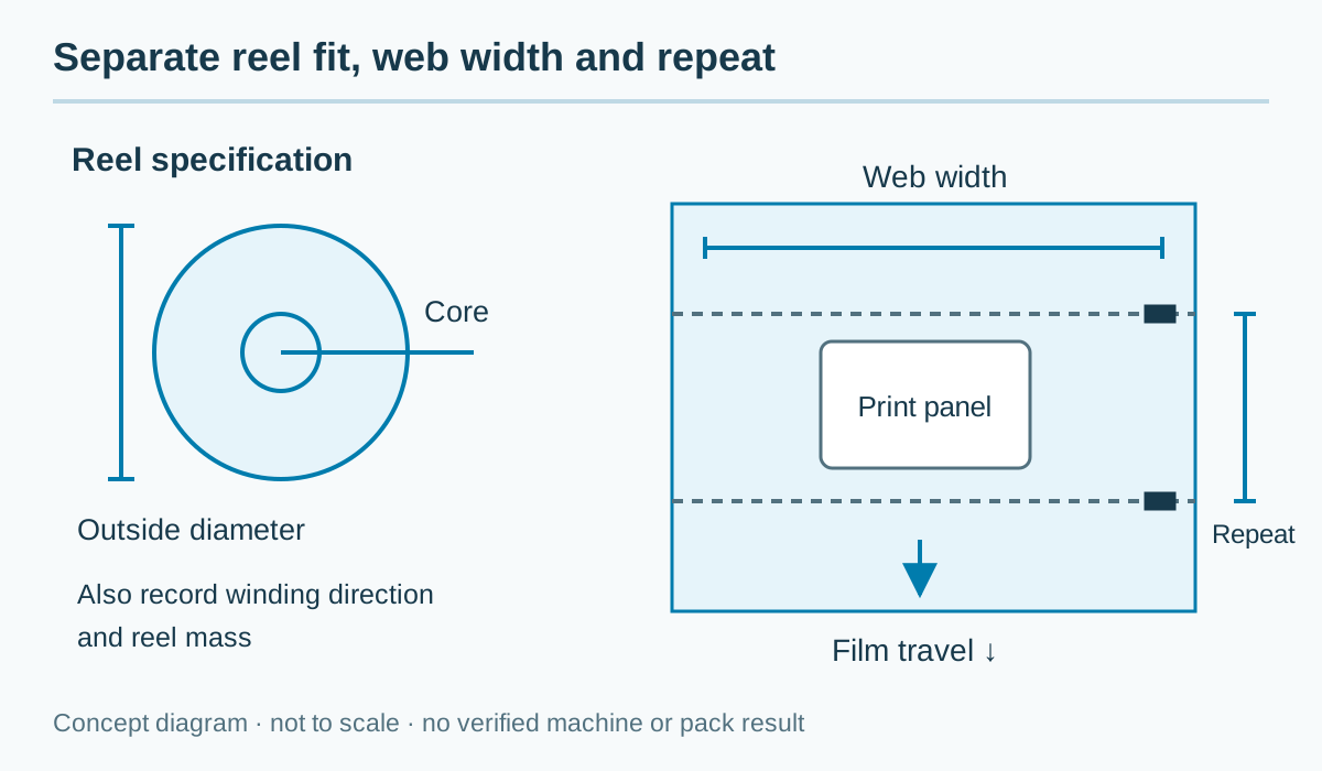
Flow Wrap Film Width and Bag Length: Sizing Guide
Measure product, flat web and cut-to-cut pack separately. Calculate developed width, reel length and film mass from the pack drawing and measured material inputs.
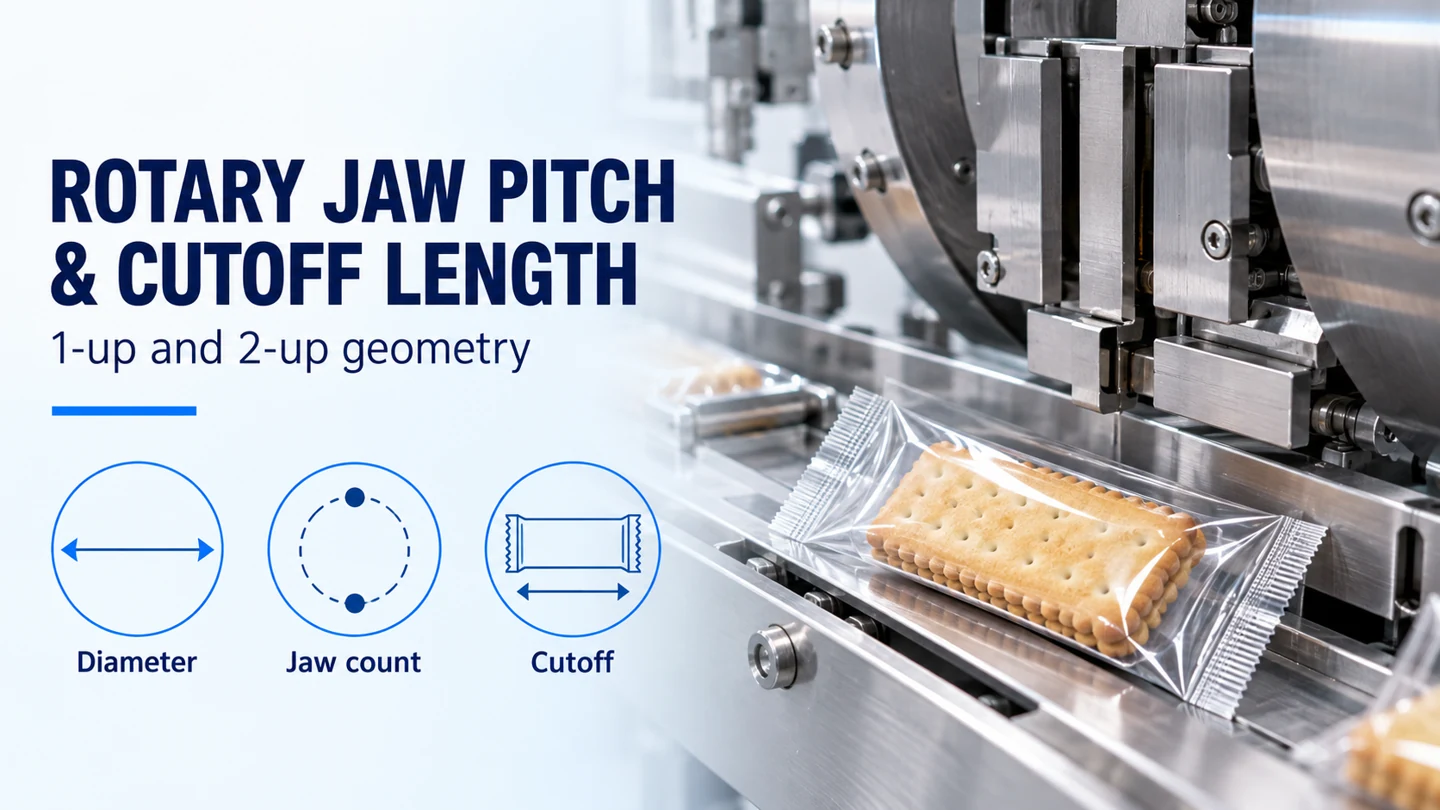
Flow Wrapper Cutoff Length: 1-Up vs 2-Up Jaw Pitch
Calculate rotary jaw pitch, distinguish shaft center distance, and compare 1-up/2-up cutoff ranges to check minimum bag length and product clearance.