
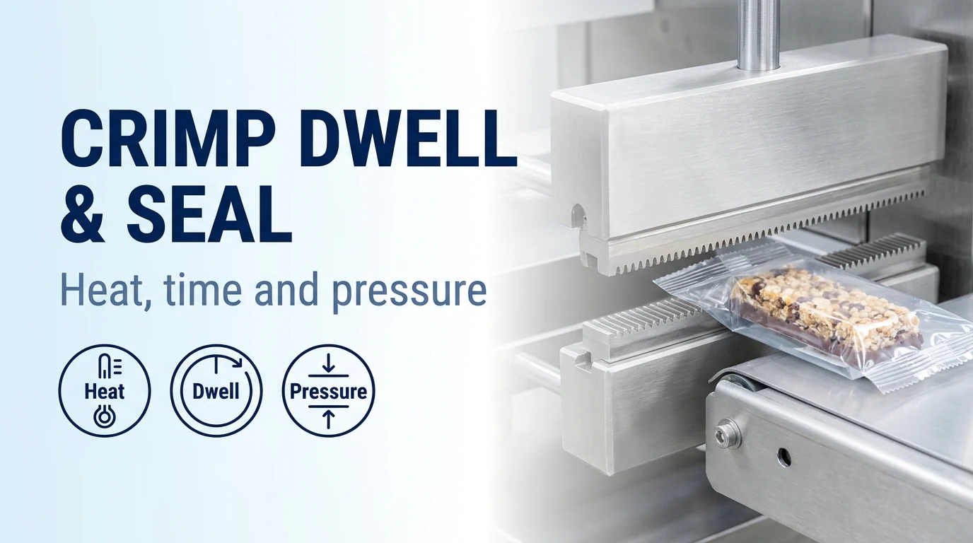
How do crimp dwell time, jaw temperature and serration pressure work together?
For flow wrap seal dwell troubleshooting, evaluate jaw temperature, contact duration and serration pressure together on your horizontal wrapper. Producing quality seals on horizontal flow wrappers requires the right combination of heat, time, and pressure, which are closely linked so adjusting one changes the others. Our horizontal flow wrapper sealing jaws are built for consistent PID temperature control, uniform serration pressure distribution, and precise shaft alignment, delivering a defined and repeatable dwell time for each film structure.
The function of heat in package sealing is to melt the sealant layer of the packaging film and bond the film together, and heat levels should remain consistent across the sealing jaw face. Time, often referred to as dwell, is the duration that the sealing jaws remain in contact with the packaging film so adequate heat can penetrate through to and melt the sealant layer. Pressure is the force that the sealing jaws apply to the film to move the melted sealant layer into open channels created by overlapping layers of film and caulk off potential leaks.
Depending on the specific film, package configuration, and running conditions, the combined total of heat, time, and pressure must fall within the optimal sealing window. If total heat, time, and pressure falls short of the optimal seal window, a quality seal cannot be achieved and significant leaks will be present. Totals of heat, time, and pressure that exceed the optimal seal window reduce seal quality and can degrade seal integrity and package appearance. Small changes in one sealing element can often be compensated for with small adjustments to another, such as offsetting a reduction in dwell time with additional heat.
Use this guide to balance rotary jaw seal dwell time, flow wrapper crimp temperature, and flow wrap end seal pressure and serration during setup. For the material specification and seam structure, see our flow wrap film guide and flow wrap packaging overview.
| Setup variable | What to record in the trial brief |
|---|---|
| Jaw temperature | Record controller setpoints and multi-point contact surface readings across the jaw face. |
| Crimp dwell time | Record line speed, cut repeat and the sealing-head motion configuration. |
| Serration pressure | Record the serration pattern, shaft clearance check and spring-tension setting. |
| Film and seam | Attach the converter specification, sealant layer details and fin-seal fold layout. |
| Seal verification | Retain labeled sample packs for leak inspection and peel-strength testing. |
Why does increasing line speed narrow the rotary seal window?
On our rotary-jaw horizontal flow wrappers, heated crimp jaws meet on the advancing film tube continuously without stopping the web, providing clean cross-seals when running heat-sealable BOPP and laminated films on uniform products. Whereas a vertical bagger or long-dwell box-motion flow wrapper typically runs around 60–80 packages per minute, our rotary end-seal flow wrappers run around 200–250 packages per minute, where shorter contact dwell times make optimizing serration pressure and jaw temperature balance across the sealing face essential.
A material's Laboratory Seal Range extends between the melt point of its core layer(s) and the lower melt point of its sealant layer, reflecting theoretical temperatures without respect to packaging conditions. The Manufacturing Seal Range accounts for sealing jaw temperature cycles as jaws transfer heat and recover, and unlike the Laboratory Seal Range, it narrows as machine speed increases and sealing time, or dwell, is reduced. A Manufacturing Seal Range study describes the relationship between sealing jaw temperature, dwell time, and force, determining the minimum dwell time and maximum machine speed that maintain proper seal integrity.
During the sealing process, temperatures are highest where the sealing jaws contact the package and dissipate as heat travels through the core layers to the sealant. Optimizing Thermal Transfer Efficiency uses heat and pressure to activate the sealant layer and move it into channels and voids to seal off leaks as quickly as possible without overheating and distorting the core layers. Thicker packaging materials require higher sealing jaw temperatures and/or more dwell time to activate the sealant layer. When running high-barrier films, multilayer laminates, recyclable mono-materials, and paper-based films, we configure extended-dwell or box-motion sealing heads so the sealant layer absorbs sufficient heat for a hermetic bond.
Compare the motion of the sealing head alongside your film structure before raising target output. Review how flow wrapping works and compare sealing motions in the flow wrapper types guide.
Film data-sheet benchmarks vs production-speed jaw temperature calibration
A material supplier's temperature window is typically determined on a lab sealer with flat, non-serrated jaws and cannot account for machine-specific dwell time, setup, and sealing jaw design.
Torayfan PMX2 metallized BOPP film has a typical Seal Initiation Temp (>200g/25mm) of 91 °C when tested on a Sentinel Sealer model 12 ASL at 0.5 sec and 20 psi. Torayfan PMX2 metallized BOPP film has a typical Heat Seal Strength @ 121°C of 430 g/25mm when tested on a Sentinel Sealer model 12 ASL at 0.5 sec and 20 psi with a flat Teflon-coated upper jaw and unheated rubber lower jaw. Torayfan PMX2 metallized BOPP film has a typical Hot Tack @ 250 °F of 210 g/25mm tested on a Sentinel Sealer with VERSATOOL hot tack attachment.
FLEXOPP B-THL standard transparent heat-sealable BOPP film has a minimum Heat Seal Strength of 300 gm/25mm at 15 micron thickness and 375 gm/25mm at 25 micron thickness by internal test method. FLEXOPP B-THL standard transparent heat-sealable BOPP film has a minimum Heat Seal Strength of 450 gm/25mm at 40, 48, and 50 micron thicknesses by internal test method. Printpack Preserve Compostable Heat Sealable Flow Wrap (2.1 mils gauge) has a typical Heat Seal Strength of 2800 g/in when sealed at 260F, 60 psi, and .25 sec.
Keep the converter data sheet with your trial record as a grade-specific reference, and establish the operating temperature window on the wrapper itself at target line speed.
To establish the minimum temperature setting on a production line, start at production speed with acceptable seal quality, drop temperature by increments of 5° F, or 3° C, until seal integrity is unacceptable, and add back 5° F (or 3° C). To establish the maximum temperature setting on a production line, increase from the original temperature setting in increments of 5° F, or 3° C, until the package is distorted or damaged, and subtract 5° F, or 3° C; the span between seal failure and seal distortion is the seal temperature window.
To verify consistent heat across the package, check temperature at multiple points along the sealing face with a contact pyrometer rather than a less accurate non-contact pyrometer. Heat profile consistency across sealing jaws can be improved with heat sink compound on heaters and thermocouples, preferentially wound heaters hotter near the ends, and more thermally conductive jaw materials. On our rotary end-sealing head assemblies, upper and lower sealing jaws pair dedicated cartridge heaters and thermocouples with independent PID control loops so temperature remains uniform across the full crimp width.
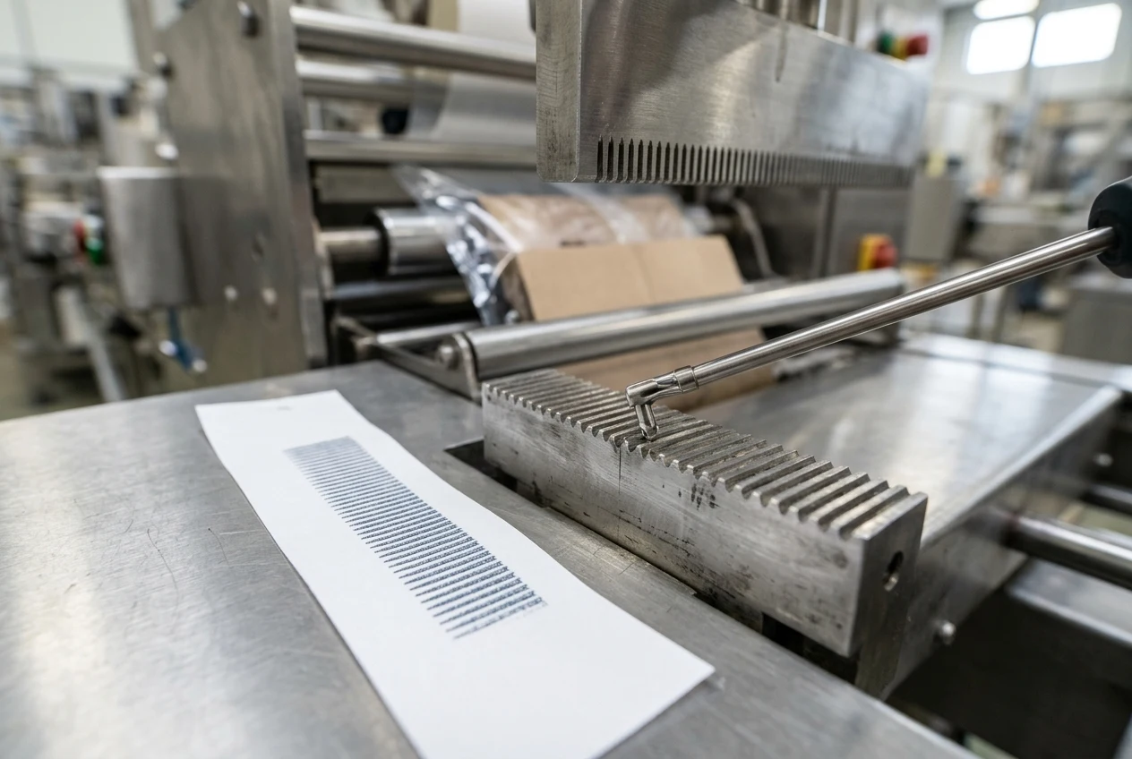
Serration geometry and caulking thickness transitions
Wider packages or wider seal widths spread force over a larger area and dilute sealing pressure, while thickness variations at the fin or lap seal, gussets, and wrinkles create gaps that are difficult to seal without distorting or damaging the package. Rotary jaw pressure levels must be high enough to initiate a seal and caulk off leakers by forcing melted sealant layer into gaps at corners, fin-seal or gusset folds, and package wrinkles, without crushing or splitting the seal.
Sealing jaw serration designs—including pitch, angle, and depth—are not universal and should be custom designed for the specific packaging material, conditions, and package configuration to maximize sealing pressure without splitting or damaging the package. When serration pressure is within its optimal range, the sealant layer melts faster and flows more efficiently to caulk potential leakers at corners and across thickness variations at the fin or lap seal, gussets, and creases.
Without maximum pressure from the serrations, more heat and time are required to produce quality seals, where higher temperature settings can damage and distort the package and longer dwell times can slow production. Serrations that are not optimized for sustainable films can contribute to split seals and reduced line speeds due to the need for longer dwell times, because limited sealant layers may not flow as readily into open areas.
When ordering replacement crimpers or trialling a new film structure with us, send us the fin-seal fold geometry and film specification so we can match the serration pitch, tooth angle, and fin-seal relief groove to the material.
Mechanical setup: shaft clearance, spring pressure and knife-bounce isolation
Sealing pressure applied by rotary sealing jaws is adjusted with springs or compression washers and is also affected by the clearance setting, sealing jaw serration design and alignment, and knife and anvil adjustment. Clearance on horizontal flow wrappers is the physical dimension between the upper and lower shaft dictated by the height of the upper and lower crimpers while the serrations are meshed together; it should be adjusted at initial set-up and generally left unchanged, though clearance may need to be fine-tuned when film structures or temperature settings are changed.
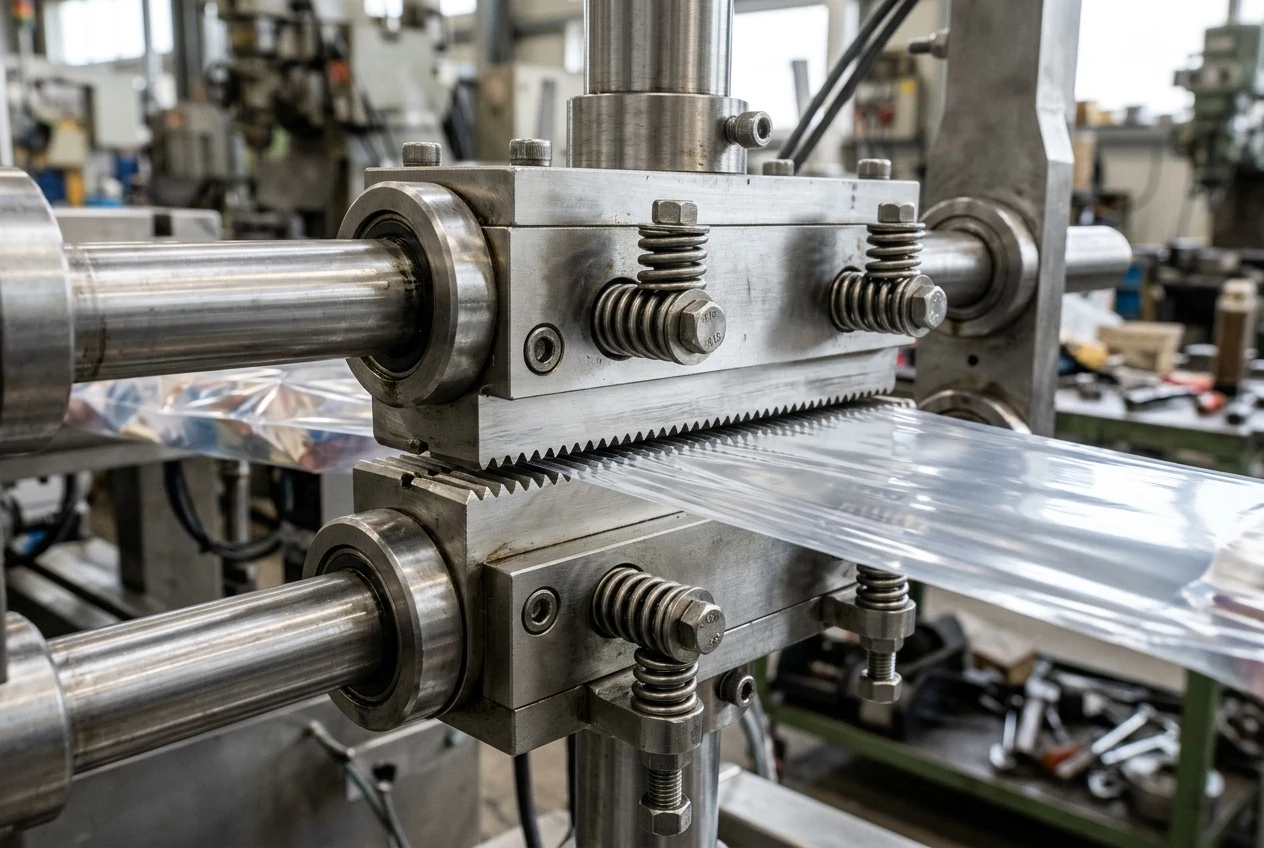
Pressure on horizontal flow wrappers refers to the spring tension between the shafts, adjusted after clearance is set so that force creates a quality cut and seal at operating temperatures and speeds without distorting or fracturing the packaging film. Mistakenly over-adjusting shaft clearance to improve seal quality or knife cutting brings the shafts too close together, producing a thumping sound and vibration when crimpers meet and causing undue wear to crimpers, knives, anvils, bearings, and shafts.
On our horizontal flow wrappers, end-sealing jaws are aligned and meshed before installing the cutoff knife and anvil (or after removing the knife first), and final alignment, shaft clearance, and nip-pressure adjustments are completed with the jaws at operating temperature before mounting bolts are fully torqued. Once jaw clearance is set so sealing faces make even contact with minimal interference, seal improvements are made by fine-tuning spring nip pressure on both sides of the head, and shifting from high to lower line speed may require reducing temperature setpoints to prevent film distortion.
Unlined carbonless paper (NCR paper) impressions reveal crimper wear, alignment imbalances, and uneven pressure across the jaw face; a slight left/right pressure difference can be magnified by limited dwell time and heat transfer (if applicable) at production speeds. On horizontal flow wrappers, if leakers occur only on the leading end seal of the package (made by the trailing sealing face of the jaws), an over-adjusted knife striking the anvil can cause the upper and lower crimpers to bounce apart and fail to transfer adequate pressure and heat. To test whether an over-adjusted knife is causing end-seal leakers, remove the knife, run sample packages with product at normal line speeds, cut them apart with scissors, and test the end seals. If crimper springs must be compressed more than half way in order to achieve a cut, the springs are worn out and need to be replaced.
How to verify seal strength under ASTM F88/F88M-15
ASTM F88/F88M-15 measures the force required to separate a test strip of flexible barrier material containing a seal and identifies the mode of specimen failure.
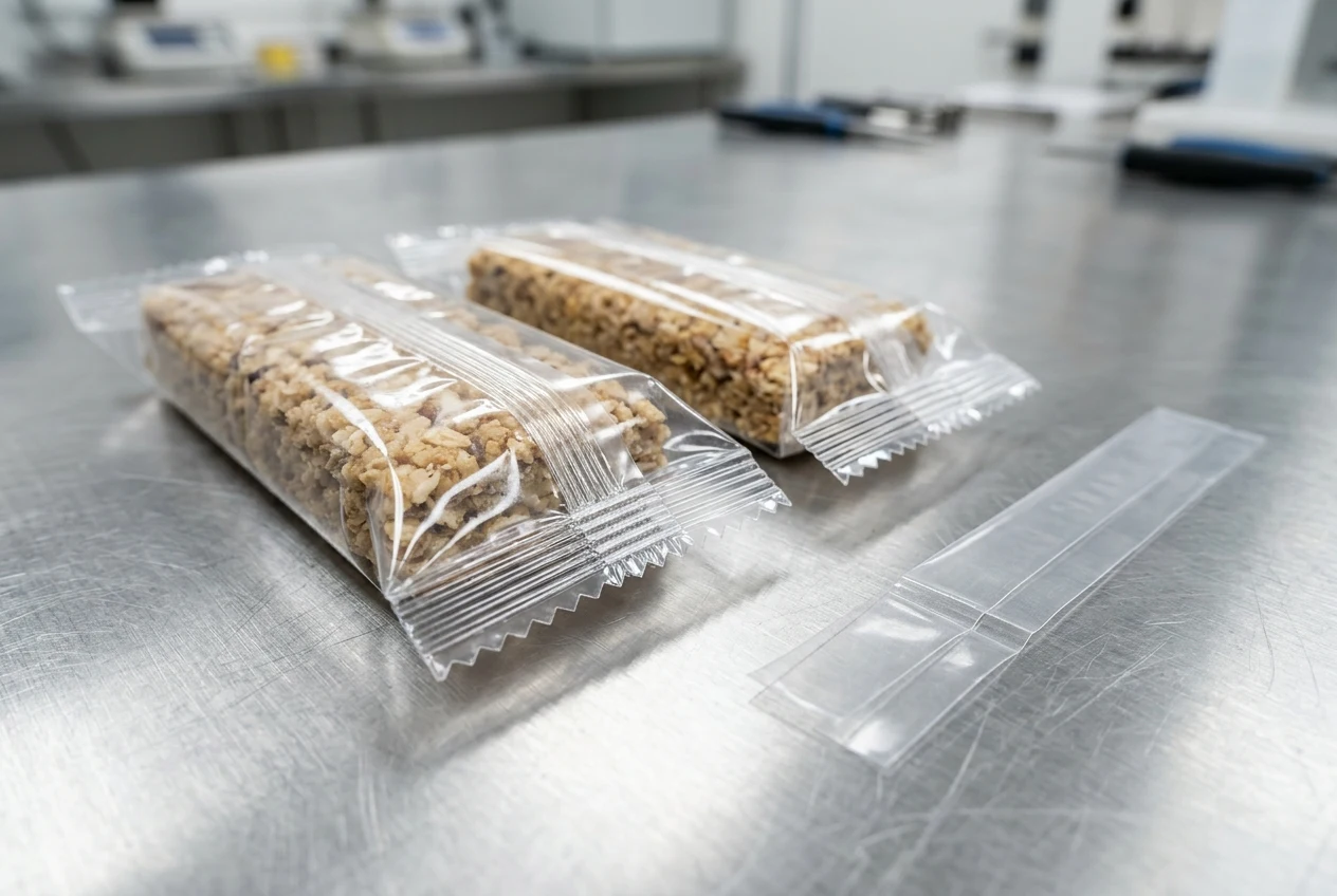
Under ASTM F88/F88M-15 Section 6.2, the specimen cutter is sized to cut test specimens to a width of 0.984 in. [25 mm], 0.591 in. [15 mm], or 1.00 in. [25.4 mm]. Under ASTM F88/F88M-15 Section 9.6 and Section 9.7, the seal is tested at a rate of grip separation of 8 to 12 in./min [200 to 300 mm/min], reporting maximum force and failure mode. Under ASTM F88/F88M-15 Section 4.2, because a bending component affects measured force, consistent use of one tail-holding technique—Technique A (Unsupported), Technique B (Supported 90° By Hand), or Technique C (Supported 180°)—is recommended throughout a test series.
Keep the specimen width, grip separation rate, tail-holding technique and failure mode recorded with each sample run so results can be compared across trials.
Prepare your rotary end-seal troubleshooting brief
Send your film structure, sealant-layer material and converter Seal Initiation Temperature data sheet, your current crimper serration pattern, your current jaw temperature setpoint and contact-pyrometer readings, and your current and target line speed with cut repeat. Attach photographs of the leading and trailing end seals, the fin-seal fold and any carbonless paper impressions. Use the film width and bag length guide and the flow wrapper requirements checklist to organize your package dimensions and trial record.
Discuss your end-seal setup on WhatsAppSources
- FlowWrapper — Horizontal Flow Wrapper Rotary & Box-Motion End-Seal Setup Guide
- Toray Plastics (America) — Torayfan PMX2 Metric Technical Data Sheet
- Flex Films — B-THL Heat Sealable BOPP Film Technical Data Sheet
- Printpack — Preserve Compostable Heat Sealable Flow Wrap Specification
- ASTM International — ASTM F88/F88M Standard Test Method for Seal Strength of Flexible Barrier Materials
Related guides
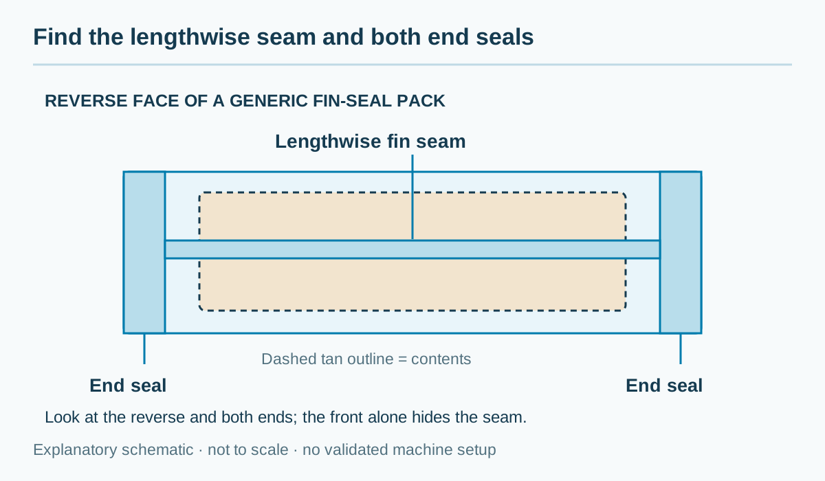
Flow Wrap Packaging: How It Works and When to Use It
Flow wrapping uses reel-fed film to make a pack with a lengthwise seal and two end seals. Check the pack format, product handling and film before choosing a machine.
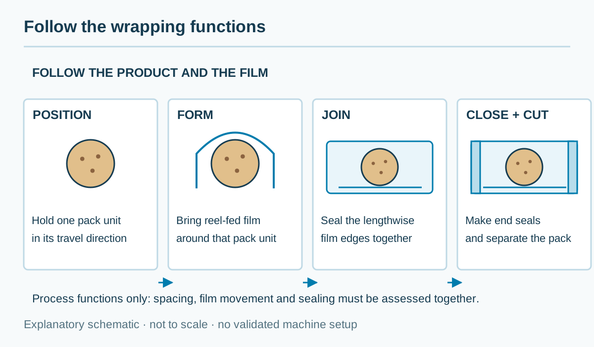
How Does a Flow Wrapper Work? Step-by-Step Process
Follow the horizontal flow wrapping process from feeding and film forming to longitudinal sealing, end sealing, cutting and finished-pack checks.
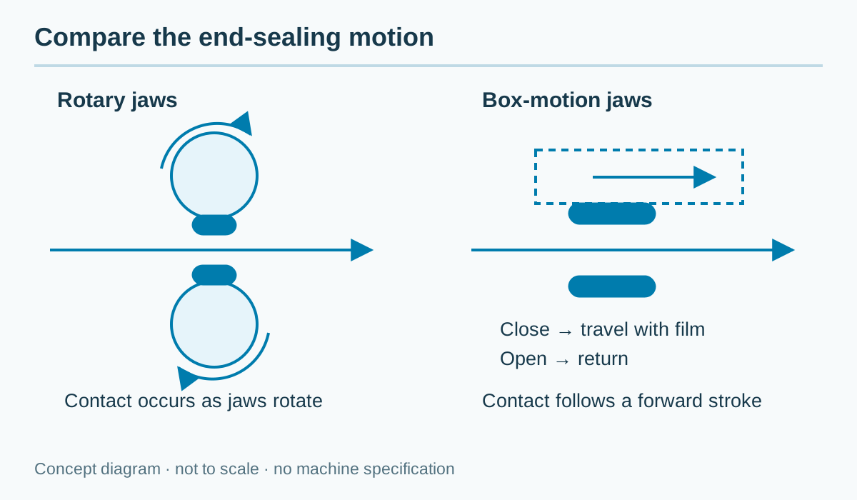
Compare Flow Wrapper Types and Configurations
Rotary or box motion? Top film or bottom film? Compare the feeding, film path and end-seal choices in a flow wrapper proposal.