
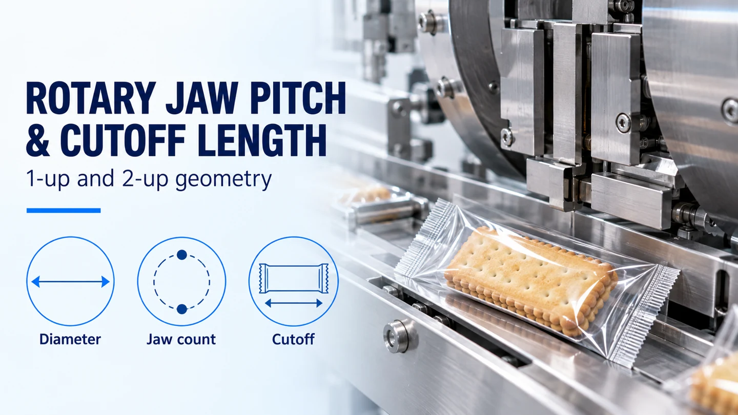
How Do You Calculate Flow Wrapper Cutoff Length?
Flow wrapper cutoff length is the film advance between consecutive cuts. For an equally spaced rotary jaw set, calculate nominal jaw pitch as P = πD / n, then compare the required pack length with the configured head's usable cutoff range. Here, D is the effective cutting-circle diameter and n is the number of stations per shaft. A 2-up head halves nominal pitch at the same diameter; its minimum usable bag length comes from the machine's operating envelope and product-clearance check.
For a documented comparison, Syntegon's Guide to Flow Wrapping, second edition (2020), lists approximate cutoffs of 140–315 mm for a 100 mm 1-up head and 85–155 mm for a 100 mm 2-up head. The guide requires testing at speed to establish exact limits. Use the calculation and table below to screen a proposed rotary configuration, then verify the product, film and jaw motion together.
| Input | Definition and source | Decision it controls |
|---|---|---|
| Effective diameter D, mm | Twice the cutting radius on the head drawing | Nominal circumferential pitch |
| Stations per shaft n | Matching jaw stations on one shaft | Cuts per revolution and angular spacing |
| Shaft center distance C, mm | Distance between upper and lower shaft axes | Head geometry and clearance review |
| Developed pack length, mm | Cut-to-cut film layout with product and seal zones | Required film advance per pack |
| Product envelope, mm | Full length, width and height, including support | Clearance through the moving jaws |
| Film and target web speed, m/min | Film specification and operating requirement | Sealing contact and motion-profile assessment |
Which Dimensions Must Stay Separate?
Cutoff, product length and jaw pitch describe different distances. Measure cutoff from one cut edge to the next along the film's travel direction. The product occupies only part of that length: film must also reach around its ends and form the transverse seals.
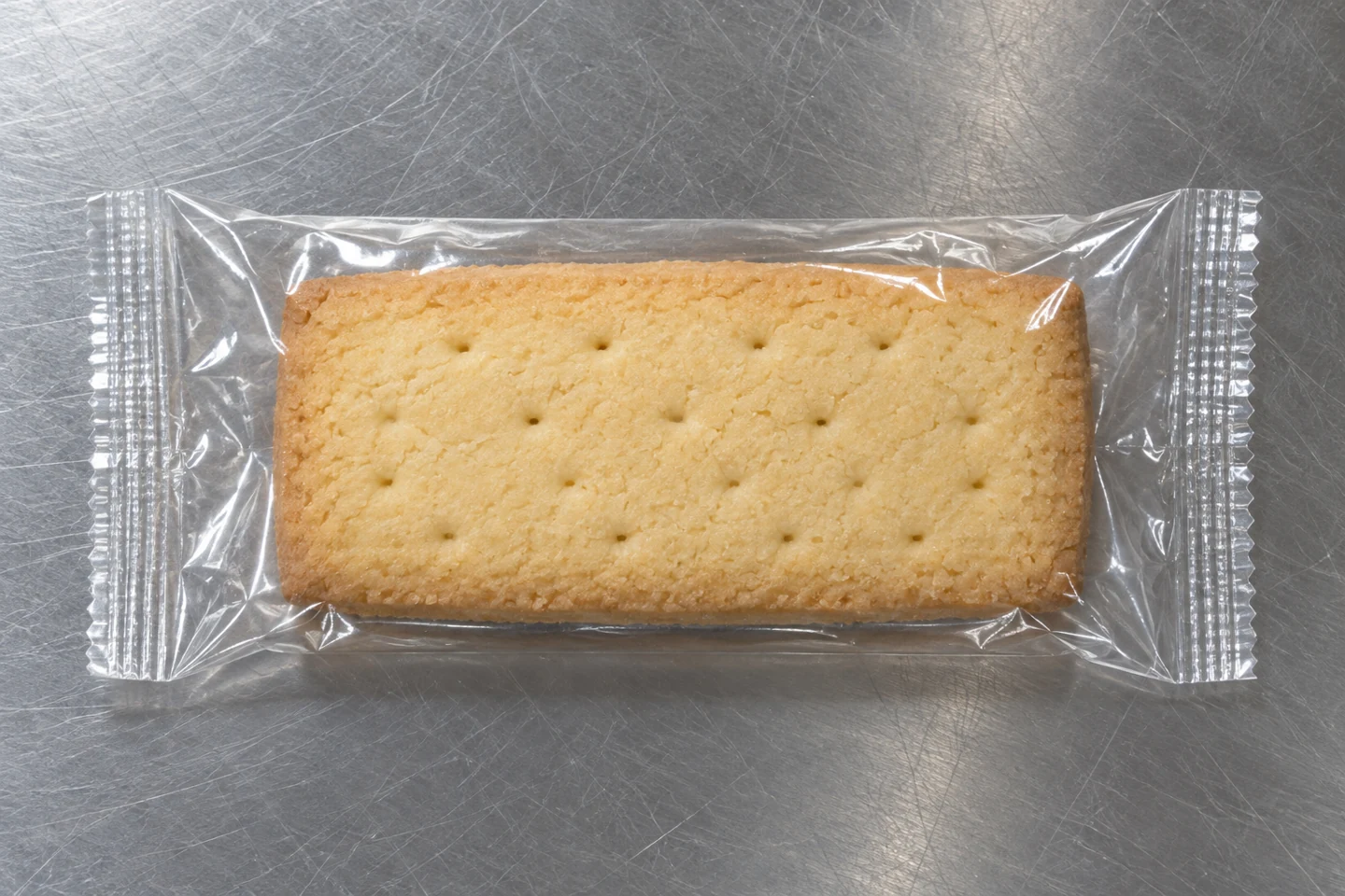
Product pitch is the distance between corresponding points on successive products along the infeed. The infeed and cutting head must synchronize their events, but the infeed's travel distance per event and the film's advance per cut need separate definitions in the machine setup.
Flow wrap jaw pitch here means the arc distance between successive stations around the effective cutting circle. Rotary seal jaw center distance means the spacing between the opposing shaft axes. Ask for both dimensions on the head drawing; a quoted “jaw diameter” without its measurement points is ambiguous.
Syntegon's 2020 guide, page 19, dimensions its illustrated cutting-head size between shaft centers. In an equal-radius opposed layout whose cutting paths meet halfway between the axes, C = 2R = D. Apply that relationship after confirming the drawing's geometry. Identify the radius to the cutting point separately from the outside radius of a holder or guard.
How Do 1-Up and 2-Up Jaw Pitch Compare?
Count stations on one shaft. A 1-up head has one crimper per shaft and one matched sealing/cutting event per revolution. A 2-up head has two equally spaced crimpers per shaft and two matched events. The upper and lower jaws that meet for one event form a pair.
For effective cutting radius R and equally spaced stations:
- Nominal arc pitch P (mm) = 2πR / n = πD / n
- Angular spacing θ (degrees) = 360° / n
Siemens' SIMATIC Rotary Knife manual, V1.5.0 (July 2025), page 9, defines the multi-knife cycle distance as cutting circumference divided by knife count. This gives a full circumference for 1-up and half a circumference for 2-up.
Diagram: scroll horizontally to read all labels.
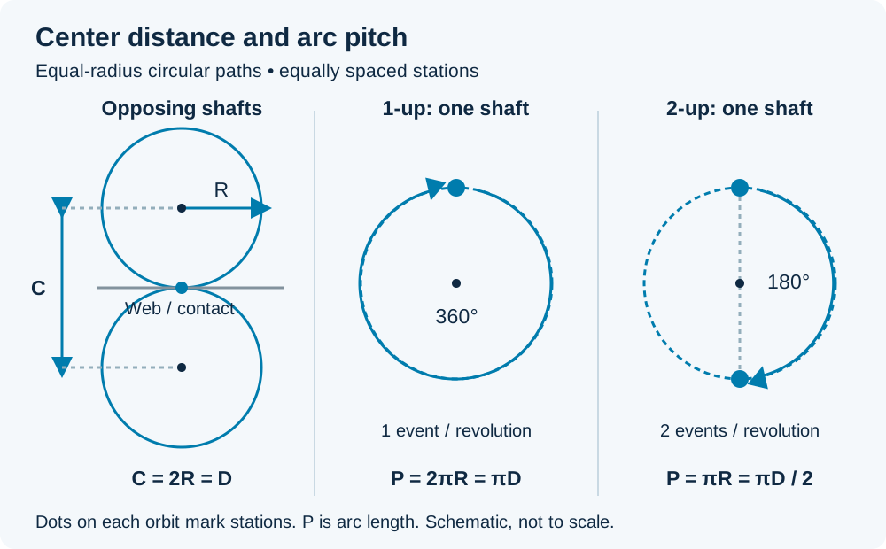
Worked calculation using the 100 mm head size in Syntegon's 2020 table and the illustrated symmetric geometry: P₁ = π × 100 mm / 1 = 314.2 mm; P₂ = π × 100 mm / 2 = 157.1 mm, rounded to one decimal place. Angular spacing changes from 360° to 180°.
| At effective D = 100 mm | 1-up | 2-up |
|---|---|---|
| Stations per shaft | 1 | 2 |
| Angular spacing | 360° | 180° |
| Calculated nominal arc pitch | 314.2 mm | 157.1 mm |
| Syntegon approximate minimum cutoff, 2020 | 140 mm | 85 mm |
| Syntegon approximate maximum cutoff, 2020 | 315 mm | 155 mm |
The calculated pitch is a geometric reference. The approximate OEM cutoff limits describe the head configuration's operating range, subject to testing at speed. Preserve each quantity when comparing a supplier's proposal.
What Sets a Flow Wrapper's Minimum Bag Length?
Minimum bag length is set by the configured head's cutoff limits together with the developed pack requirement and moving clearance. Nominal pitch alone cannot supply all three checks. The source table illustrates this directly: the 100 mm 2-up head has a calculated nominal pitch of 157.1 mm and an approximate minimum cutoff of 85 mm.
The following is a representative OEM reference from Syntegon's Guide to Flow Wrapping, second edition (2020), page 20. Cutoff limits are approximate; the guide requires actual machine testing at speed to establish exact minimum and maximum cutoffs.
| OEM head size | 1-up cutoff range | 2-up cutoff range | Listed maximum product height, both configurations |
|---|---|---|---|
| 100 mm | 140–315 mm | 85–155 mm | 40 mm |
| 120 mm | 170–375 mm | 90–185 mm | 60 mm |
| 150 mm | 200–470 mm | 110–235 mm | 90 mm |
| 180 mm | 250–565 mm | 130–280 mm | 110 mm |
Read each row as a configuration reference. Have the supplier confirm the combination of product height, cutoff, film and speed for the proposed machine. The height and cutoff endpoints need to be assessed together with the jaw path and product position.
For short packs, 2-up can provide a lower cutoff range within a given head size. The same table also shows a lower maximum cutoff for 2-up. A project with both short and long formats therefore needs a format-by-format review of jaw tooling and motion limits.
Does Your Target Cutoff Fit the Product and Head?
A candidate cutoff must fit both the developed pack layout and the supplier-confirmed range. Let L_layout be the required cut-to-cut length from the developed film drawing, L_min,cfg and L_max,cfg be the confirmed limits for the proposed configuration, and L_target be the selected cutoff. All lengths use the same unit:
max(L_layout, L_min,cfg) ≤ L_target ≤ L_max,cfg
If the lower bound exceeds the upper bound, the proposed layout and head have no usable overlap. Reassess the pack layout or head configuration before specifying the film repeat. If the range overlaps, continue with the swept-clearance check: the space occupied by the jaws and the moving product throughout the cycle.
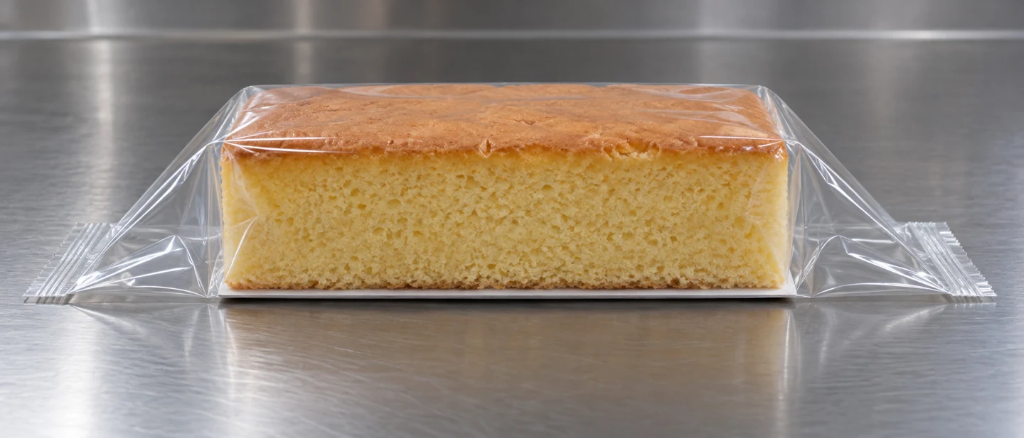
Start with the film-width and bag-length layout. Include the end transitions, seal bands and cut position explicitly. Syntegon's 2020 guide, page 21, includes product height in its starting cutoff estimate and calls for actual product-and-film testing. Simply adding product length to two seal widths leaves the end-transition geometry unresolved.
Then use the complete product-envelope measurements, including the tray, card, grouped items and dimensional variation. A static gap between open jaws is only one position in the cycle. Review the jaw trajectory relative to both ends of the product as it passes through.
If the proposed rotary head cannot accommodate the layout and film contact requirements, compare the rotary and box-motion flow wrapper types with the same product and pack inputs.
Why Can Cutoff Differ From Circumferential Pitch?
A suitable rotary motion profile matches the film through the contact region and changes speed between contacts. This allows the film advance per cut to differ from the nominal circumferential pitch.
For a shorter cut, the head completes the return interval faster before matching the film again. For a longer cut, it moves more slowly between contacts or pauses where the mechanism permits. ABB's Rotary Knife (PLCopen motion), AN00253 Rev B, and Siemens' SIMATIC Rotary Knife, V1.5.0, describe this separation between the synchronized cutting region and the compensating motion region.
The available acceleration, deceleration and contact interval constrain the achievable format at the selected web speed. That is why the supplier needs the target cutoff and speed together when assessing the head. Check seal contact and product clearance at the same operating point.
Cut length and shaft rotation also connect through cuts/min = 1,000 × web speed (m/min) / cutoff (mm) and mean shaft rpm = cuts/min / n. Use these as kinematic rates; verify accepted-pack output through the agreed production trial.
Is the Fault Geometry, Product Timing or Cutoff Drift?
First distinguish stable pack length with misplaced product from changing pack length. The first directs attention to product position, phase and clearance; the second also calls for film-transport and control checks. Retain consecutive packs so a repeated pattern is visible.
| Observation | Checks to prioritize | Useful record |
|---|---|---|
| Consistent cutoff, product catches a jaw | Product placement, infeed timing, jaw phase and swept clearance | Pack sequence and guarded motion video |
| Short or tall format contacts the jaws | Developed length, full product height and configured cutoff envelope | Product and head drawings with motion path |
| Cut-to-cut length varies | Film slip/tension, actual web travel, recipe and axis following error | Sequential length readings with speed and recipe |
| Printed artwork shifts relative to the cut | Mark detection, registration settings and web transport | Film repeat specification and successive cut positions |
PacMatix's Flow Wrapper Troubleshooting: 10 Common Faults & How to Fix Them separates product crushing, cutoff inconsistency and registration faults. Siemens' V1.5.0 manual, FAQ 6.6, also addresses cut-length errors during acceleration and at constant speed. Use the observed pattern to focus the investigation. Any inspection inside guarded machinery belongs under the manufacturer's isolation and service procedure.
What Should You Verify Before Approving the Format?
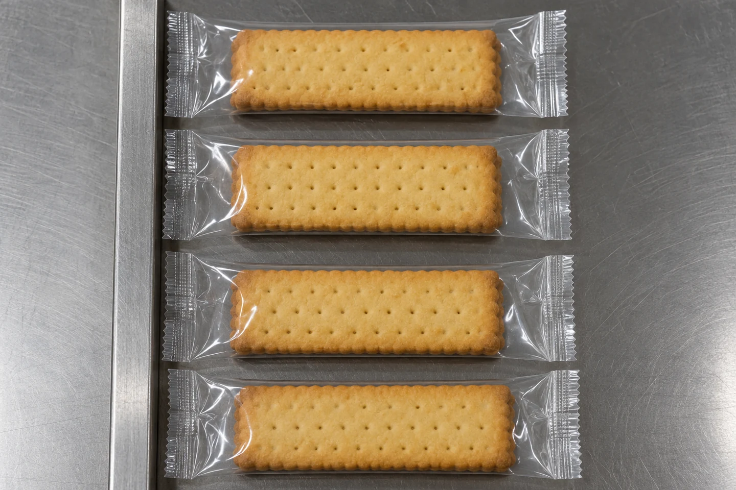
Verify the exact product, film, jaw set, cutoff and target speed together. Record the actual cut lengths and where both end seals sit relative to the product. A useful trial record connects the pack measurements to the machine configuration and running conditions.
- Identify the head drawing, effective cutting diameter, shaft centers and stations per shaft.
- Record the developed pack length, product size range, support and end-seal widths.
- Confirm the proposed cutoff range with the supplier for that jaw set, film and speed.
- Check product clearance through the full jaw cycle and inspect the seal/cut zones.
- Retain consecutive packs with measured cutoff, product position, seal findings and any contact or rejected packs. Agree the measurement method and acceptance limits before approving the format.
Discuss your cutoff and jaw configuration on WhatsApp
. Send product length and height, end-seal widths, target bag length, film details and target line speed so the team can assess the configuration and sample-test requirements.
Questions About Multi-Jaw Configurations
How does the calculation extend to a 4-up head?
For four equally spaced stations per shaft, nominal arc pitch is πD / 4 and angular spacing is 90°. Obtain the 4-up tooling limits and clearance drawing for the proposed machine, then apply the same layout, operating-range and moving-clearance checks.
Does changing from 1-up to 2-up double production?
A 2-up arrangement gives two cutting events per shaft revolution. Accepted output still depends on feeding, film transport, the available motion profile, sealing contact and product clearance. Compare the two configurations at the required pack length and quality criteria.
Can a bag-length recipe change substitute for a different jaw set?
The recipe selects a length within the configured machine’s operating envelope. A format beyond that envelope requires a supplier review of tooling, motion limits and product clearance. Confirm the supported formats before changing hardware or ordering printed film.
Technical References
- Syntegon, Guide to Flow Wrapping, second edition, 2020: pages 19–21 for head geometry, approximate cutoff ranges and pack sizing; page 24 for product-position faults.
- Siemens, SIMATIC Rotary Knife, Entry ID 109757260, V1.5.0, July 2025: page 9 for multi-knife geometry, “Geometry and Function” for motion profiles, FAQ 6.6 for cut-length inaccuracies.
- ABB, Rotary Knife (PLCopen motion), AN00253 Rev B: circumference scaling, multiple knives and short/long cut compensation.
- PacMatix, Flow Wrapper Troubleshooting: 10 Common Faults & How to Fix Them: product crushing, cutoff variation and print registration.
Related guides
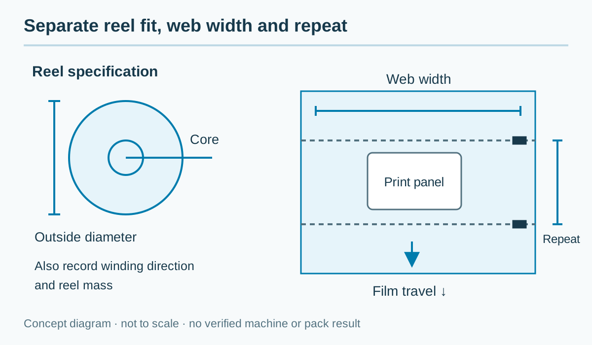
Flow Wrap Film Width and Bag Length: Sizing Guide
Measure product, flat web and cut-to-cut pack separately. Calculate developed width, reel length and film mass from the pack drawing and measured material inputs.
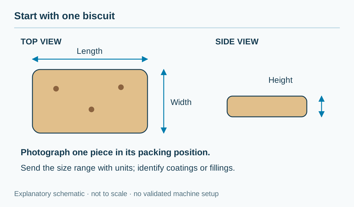
How to Size a Flow Wrapper for Your Product
Measure real product length, width and height, including trays and groups, then review the infeed, forming section, film and end-sealing clearance together.